On the good channel R5 R6 R7 and R8 all have about 18-20R across them.
On the bad channel R5 and R7 have zero R and R6 and R8 have 18-20R across them....
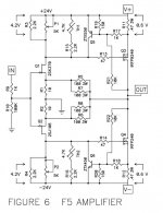
Could you post the schematic that you are using?
Attachments
Was your R5 marked as a 100R and wasn't? If so, it was damaged along with the R1,
probably due to high DC output voltage. Check that the DC offset voltage is small.
Or was R5 actually the wrong value part? I always first measure each part that I install on a board.
probably due to high DC output voltage. Check that the DC offset voltage is small.
Or was R5 actually the wrong value part? I always first measure each part that I install on a board.
Last edited:
Was your R5 supposed to be 100R and wasn't? If so, it was damaged along with the R
No I installed an incorrect R value for R5... .13E blue ohmite looks just like 100R blue ohmite..until you read the fine print. That explains why this channel has never worked...I hope.
No I installed an incorrect R value for R5... .13E blue ohmite looks just like 100R blue ohmite..until you read the fine print. That explains why this channel has never worked...I hope.
Wrongly binned parts happen, always measure first. There's no way the amp could have worked with 0.13R in there.
Be sure to replace R1 also. The R7 will be fine, since it was protected by a short across it.
Last edited:
amp is warmed up.....getting .6v bias both channels no problem.....and can't get much lower than about 12ma DC offset...pretty happy!
...of course the above should be mV...not ma....
Well....both channels have a fair bit of hum...
On the bench I'm not seeing it with the scope cranked all the way up..but downstairs in the system it's obvious.
I'm measuring 4 ohms from the common ground point on the boards where the PS, RCA and speaker grounds are all connected together ........ to the chassis ground stud.....is this typical or too much R?
I tried clip leads from the PCB ground to the stud..speaker -ve to the stud and RCA -ve to the stud..no change. RCA's are insulated from the chassis..with -ve grounded at the PCB.
I have twisted pair wires running from RCA's to the PCBs...no coax...
any suggestions?
What are you driving the amp with?
Anthem Pre-1 tube preamp....no hum with other power amps....
Sounds very much like 60 Hz hum...
Sounds very much like 60 Hz hum...
You likely need a loop breaking 10R resistor from each input RCA ground to the the audio ground,
in place of the wires that serve that function now. These resistors are often necessary, depending
on exactly how the components are built.
10R didn't help...and as it turns out, it's now only in the channel that had the issue above.
Then it may be inductive hum pickup from the internal components or wiring.
Does it still hum with shorting plugs in the RCAs? Can you post photos of the layout?
Then it may be inductive hum pickup from the internal components or wiring.
Does it still hum with shorting plugs in the RCAs? Can you post photos of the layout?
That's what I'm thinking too......still hums when shorting inputs....
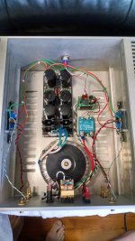
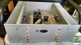
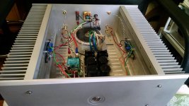
Here are some pics....the little stacked PCB assembly and SSR are to support use of a Fancy Bulgin momentary switch. This chassis was used for years as an F4 without issues..
Attachments
The simplest first thing to try is to disconnect the long input RCA wiring, and add an input short
right on the audio boards. If the hum goes away, there is 60Hz hum pickup from the transformer,
which is right in the middle of all the wiring.
..ok...be right back....
ok..unsoldered the RCA inputs at the PCBs....
...left the RCA grounds connected.....
On the good channel, it's quiet regardless of whether I touch the RCA input wire to the pad on the board or not.
On the noisy channel, it looks just like the quiet channel with the wire diconnected..when I touch that wire to the pad on the PCB it looks really noisy.
When it was an F4 I had coax for the inputs..I'll replace the twisted pair with a coax on the noisy channel.
- Status
- This old topic is closed. If you want to reopen this topic, contact a moderator using the "Report Post" button.
- Home
- Amplifiers
- Pass Labs
- F5 troubleshooting