Observe this black magic: Here's a link to post #89 that works equally well for people who view 10 posts/page, and for people who view 50 posts/page
voila -- here is post 89
Tried it just now in Opera, Chrome, Internet Explorer, and Firefox. Turkey Worky all four times.
+ _
voila -- here is post 89
Tried it just now in Opera, Chrome, Internet Explorer, and Firefox. Turkey Worky all four times.
+ _
Last edited:
Itsmee,
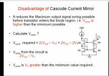
Your current mirror of choice is a cascode current mirror. It has a problem in the it reduces the maximum output voltage swing. It is best used in pre-amp circuits where you signal is not required to swing close to the rails.
The way around this is a folded cascode current mirror..........but the complexity?
Jam
Attachments
Last edited:

Hijack?
Itsme,
I think (hope) Jeff looks upon this thread as a forum to explore ideas for his amplifier and I would think any exchange of ideas would be fine. I am curious to see what topology he picks for the JamJar.
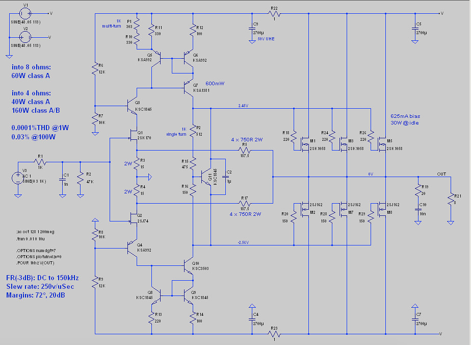
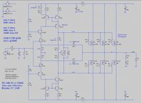
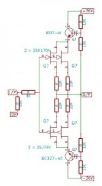
Apart from the Sony topology the one attached has some possibilities. I would look at the use of current sources and improved mirrors. It is based on Hitachi app. notes for their mosfet's and was used by Goldmund and Perraux. I think the orignal desing belongs to Tektronix or HP for use in scope front ends.
It can be marginally unstable if not correctly compensated but when optimized can sound excellent......low distortion......wide bandwidth.......and excellent slewing characteristics.
Itsme,
I think (hope) Jeff looks upon this thread as a forum to explore ideas for his amplifier and I would think any exchange of ideas would be fine. I am curious to see what topology he picks for the JamJar.
Apart from the Sony topology the one attached has some possibilities. I would look at the use of current sources and improved mirrors. It is based on Hitachi app. notes for their mosfet's and was used by Goldmund and Perraux. I think the orignal desing belongs to Tektronix or HP for use in scope front ends.
It can be marginally unstable if not correctly compensated but when optimized can sound excellent......low distortion......wide bandwidth.......and excellent slewing characteristics.
Attachments
Last edited:

Believe it or not!
Now tell me this isn't true......................DIY at it's best.
Giant Vegemite Jar Cake | HOW TO CAKE IT
Now tell me this isn't true......................DIY at it's best.
Giant Vegemite Jar Cake | HOW TO CAKE IT
Last edited:
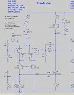
Just to catch up a little, I did a revision of the original current-mirror version, incorporating some of the ideas posted:
And I did a second version using the front end from Nelson's Sony VFET article. Interestingly all the SPICE metrics on it are worse than the current mirror version. They probably line up reasonably well with Nelson's measurements, although it's a bit hard to compare SPICE numbers and real numbers.
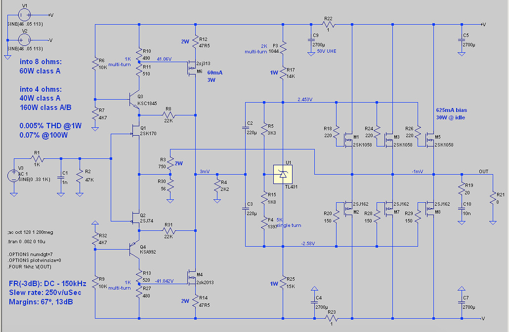
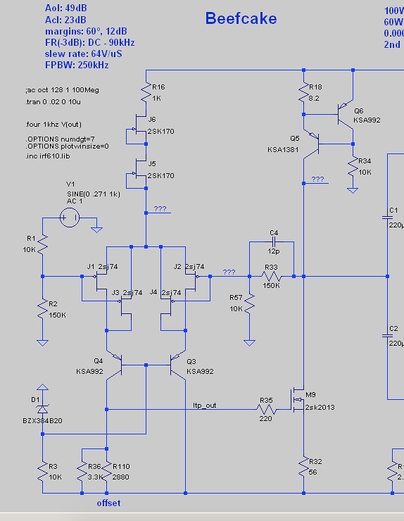
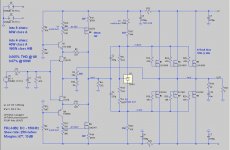
I also took some time to whittle down the Sony schematic Jam posted, and minus the temp comp stuff it's actually not that hard to understand (although I'm still trying to get my head around that BJT/MOSFET VAS). In fact, it's sort of an upside-down version of the topology I'm using in my Beefcake front end (and with different CCS implementations):
I still mean to look into some other ideas, such as Patrick's headphone amp, but you guys are hard to keep up with.
Cheers,
Jeff.
PS: no worries on thread hijacking. It's all good stuff.
And I did a second version using the front end from Nelson's Sony VFET article. Interestingly all the SPICE metrics on it are worse than the current mirror version. They probably line up reasonably well with Nelson's measurements, although it's a bit hard to compare SPICE numbers and real numbers.
I also took some time to whittle down the Sony schematic Jam posted, and minus the temp comp stuff it's actually not that hard to understand (although I'm still trying to get my head around that BJT/MOSFET VAS). In fact, it's sort of an upside-down version of the topology I'm using in my Beefcake front end (and with different CCS implementations):
I still mean to look into some other ideas, such as Patrick's headphone amp, but you guys are hard to keep up with.
Cheers,
Jeff.
PS: no worries on thread hijacking. It's all good stuff.
Attachments
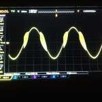
I don't like the version I posted as much as an earlier incarnation, 24V rails, no cascode and JFET output, but it had swing problems as Jam pointed out with the mirror, increasing the rails to compensate meant cascoding the input and output, I ran into problems with the cascode output, see pic, I could drive above and below without problems, but at a particular level it was unstable, I changed it to the MOSFET output which I know would drive pucks, it sounds too laid back, I need to look at the THD spectra.
Attachments
Hi Jeff,
In post 32 I would cascode the VAS mosfet but in my humble opinion the circuit in post 26 work the best in your application. The secret being the current mirror in the second differential.
Jam
Hi Jam,
The single-ended VAS MOSFET in the Beefcake, or the push-pull VAS MOSFETs in the middle schematic? (I assume the Beefcake one?)
I need to look at post 26 more. I've played around a lot with the Naim NAP circuit, so I'm no stranger to marginal stability. It would need a new name, though. It's coming up on pumpkin pie time....
Cheers,
Jeff.
Now tell me this isn't true......................DIY at it's best.
Giant Vegemite Jar Cake | HOW TO CAKE IT
Wow that was bloody good.
I am relieved to know they didn't actually use vegemite in the cake, that would be a BAD idea. Hahahaha
A couple more from John Linsley Hood
https://sound-au.com/tcaas/WW8-82.gif
https://sound-au.com/tcaas/EWW3-89.gif
https://sound-au.com/tcaas/WW8-82.gif
https://sound-au.com/tcaas/EWW3-89.gif
- Home
- Amplifiers
- Pass Labs
- JamJar: an HPA-1-inspired power amp