ACP+ Prototype.
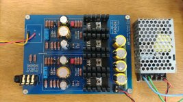
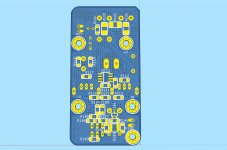
I have built own PCB, mostly kept same design as Mr. Nelson Pass' but with smaller size to use hammond chasis.
From smoke test, I failed with one channel, R13 was burnt.
I have disassembled R13, J74 and Optocoupler. Optocoupler itself is okay, but when it is connected to board (without J74 and R13) the voltage across R13 differs for two channels. (One with 23.96V, the other is 23.74V)
I will try with new Optocoupler from On-semi. (Previous one from Vishay)
Is there anything else should I check?
I didn't matched j74, not even measured Idss, since I had only four in the drawer. Is Idss matching critical for this design? (Using V variant)
Attachments
No Sibling Rivalry
Great to see that so many of these are getting built!
I had been using the ACP+ for several months as a HP amp with some 32 ohm planars. It became my "go to" amp with those phones.
I recently had a bit of time to swap out some equipment "just to see". I had seen that the ACP+ had been referred to as a "mini-J2". So, for grins, I put the ACP+ in as a pre-amp with ZM's Babel J2.
I still don't know exactly what contributes to great sound, or why. Before DIY, I was in the camp of "bigger must be better" and all the other audiophile nervosusussses (nervosi?) This "little" thing with a switching power supply and "stock" parts is absolutely brilliant. I'm starting to try and understand some of the commonalities among circuits that I personally like and think work well together. IMHO, everything I've built sounds wonderful. But... finding a neat combination that just sings and makes me grin from ear to ear is what it's all about.
I hope everyone out there is happy and healthy. Thanks again to Papa for his unending generosity and all the others out there who've taught me along the way. I sure do love having some exceptional tunes while I'm "self-isolating".
Here's a pic of "the kids"


Great to see that so many of these are getting built!
I had been using the ACP+ for several months as a HP amp with some 32 ohm planars. It became my "go to" amp with those phones.
I recently had a bit of time to swap out some equipment "just to see". I had seen that the ACP+ had been referred to as a "mini-J2". So, for grins, I put the ACP+ in as a pre-amp with ZM's Babel J2.
I still don't know exactly what contributes to great sound, or why. Before DIY, I was in the camp of "bigger must be better" and all the other audiophile nervosusussses (nervosi?)
This "little" thing with a switching power supply and "stock" parts is absolutely brilliant. I'm starting to try and understand some of the commonalities among circuits that I personally like and think work well together. IMHO, everything I've built sounds wonderful. But... finding a neat combination that just sings and makes me grin from ear to ear is what it's all about.I hope everyone out there is happy and healthy. Thanks again to Papa for his unending generosity and all the others out there who've taught me along the way. I sure do love having some exceptional tunes while I'm "self-isolating".
Here's a pic of "the kids"
I have built own PCB, mostly kept same design as Mr. Nelson Pass' but with smaller size to use hammond chasis.
From smoke test, I failed with one channel, R13 was burnt.
I have disassembled R13, J74 and Optocoupler. Optocoupler itself is okay, but when it is connected to board (without J74 and R13) the voltage across R13 differs for two channels. (One with 23.96V, the other is 23.74V)
I will try with new Optocoupler from On-semi. (Previous one from Vishay)
Is there anything else should I check?
I didn't matched j74, not even measured Idss, since I had only four in the drawer. Is Idss matching critical for this design? (Using V variant)
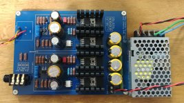
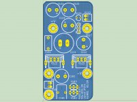
I found error from my PCB design and finally get it work.
No noise at all.
Next step is listening test and placing an order of new PCB with fixes.
Attachments
Hi Mr. Pass,
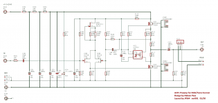
JPS64 has also developed a nice layout of the ACP+ to be compatible with the M2X front end module bolt pattern. We will provide the Gerber files here, and also offer the PCBs to the community for cost of manufacturing and shipping/handling. The boards will use some large SMT parts on the underside to keep things compact. Through hole parts on top. Please let us know if you are good with this.
Thank you.
xrk971 & JPS64
Attachments
Last edited:


Hello members,
I downloaded KiCad 4 days ago. I had a lot to read about the software -
and to try...
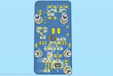
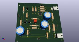
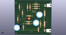
I thought a good first project could be the layout of the ACP+ preamp.
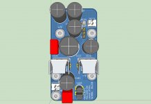
I show the 3D-view. I hope you won't shake with laughter
It was my first time...
And I wanted the MosFets in that direction...
And the board is bigger than necessary...
The 'covid'-crisis has a positive aspect - I learn something new!
Greets
Dirk
I downloaded KiCad 4 days ago. I had a lot to read about the software -
and to try...
I thought a good first project could be the layout of the ACP+ preamp.
I show the 3D-view. I hope you won't shake with laughter
It was my first time...
And I wanted the MosFets in that direction...
And the board is bigger than necessary...
The 'covid'-crisis has a positive aspect - I learn something new!
Greets
Dirk
Attachments
I thought a good first project could be the layout of the ACP+ preamp. ... It was my first time...
BRAVO!! That's just outstanding! Congratulations upon your success, and even greater congratulations for your courage to try something new.
You have become a shining example to other diy'ers. Laying out PCBs is not impossible; just look at Dirk! He taught himself to do it. Anyone else can, too.
to ItsAllInMyHead #276
Hello ItsallInMyHead,
thanks for the kind words! I have to learn much more.....
I feel myself at a knowledge-level below sea-level....
Or - let's say - in the lowest basement of electronics.
And still searching for the light switch in the basement
Enjoy your amps and music!
Greets
Dirk
Hello ItsallInMyHead,
thanks for the kind words! I have to learn much more.....
I feel myself at a knowledge-level below sea-level....
Or - let's say - in the lowest basement of electronics.
And still searching for the light switch in the basement
Enjoy your amps and music!
Greets
Dirk
Hadn't seen this - great that you got it working!!Thank You Nisbeth!
I've built up a unit with Nisbeth's boards
and everything is working fine.
Bruce
Hi Mr Pass,
Just bumping this question since you have not responded yet.
Thanks,
X
Just bumping this question since you have not responded yet.
Thanks,
X
Hi Mr. Pass,
JPS64 has also developed a nice layout of the ACP+ to be compatible with the M2X front end module bolt pattern. We will provide the Gerber files here, and also offer the PCBs to the community for cost of manufacturing and shipping/handling. The boards will use some large SMT parts on the underside to keep things compact. Through hole parts on top. Please let us know if you are good with this.
Thank you.
xrk971 & JPS64
then build something else ...... without JFets
How about ZVP3310 for the LTP (Q1 & Q2), considering that J74 are soooo difficult to find (the real ones)?
Considering that this can be built on a strip board without much difficulty.
- Home
- Amplifiers
- Pass Labs
- Amp Camp Pre+Headphone Amp - ACP+