Gaz2613 - there are no more boards currently.
There will be more.")
When?
I'll give that a try after noticing the sanding marks on the pics. I am not a great painter....
Hifi2000 can also print on the panel. I probably should have gotten that instead of engraving.
Hifi2000 can also print on the panel. I probably should have gotten that instead of engraving.
At BAF, Gianluca took time with me to make it clear that their painting process turns out a better finish for small text. One to keep in mind..
Here you go. Enjoy!
Thank you genechow!
I'll give that a try after noticing the sanding marks on the pics. I am not a great painter....
Hifi2000 can also print on the panel. I probably should have gotten that instead of engraving.
At BAF, Gianluca took time with me to make it clear that their painting process turns out a better finish for small text. One to keep in mind..
That's correct, if your text is small I would definitely suggest to go for digital printing instead of engraving. The good thing about printing is that we can also make the text of any color you want, it does not have to be black
Yes, I can also confirm this, here a sample! Greetings to Gianluca!
(please click on the pic for correct dimensions). :-|
Greetings to Gianluca!An externally hosted image should be here but it was not working when we last tested it.
(please click on the pic for correct dimensions). :-|
Nisbeth, if you decide to create (lay out) a new improved printed circuit board for the ACP+, including those two trimmer potentiometers you mentioned, please permit me to offer a couple of suggestions for additional modifications that you might want to think about incorporating:
>snip<
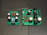
Well I did do a clone, but I didn’t really implement any of the things you suggested – sorry Mark 😉 Took a bit longer to arrive than planned because boards and parts were delayed, but now it is (nearly) completed.
Highlights: Amplifier boards are separate mono channels, PSU is a separate board and volume control is separate (offboard) as well. For the amp I’ve chosen a different heat sink profile, and also made some tweaks to the parts footprints in some places. Last but not least the headphone/line outputs are both on the board along with a tiny relay to allow switching between them.
I’m still missing the relays so no full testing yet, but the amp biases as expected and it plays clean audio – never a bad start 😊
Apologies for the crappy pic - this time of the year I'm only really home when it is dark outside
Attachments

I have a question, with these single rail unbalanced amps there is a need for an output cap which needs to be charged to about half the rail voltage for max swing. To avoid a massive turn-on thump it needs to come up slowly and Mr. Pass seems to find simple and elegant ways to do this without additional active parts or muting relays, certainly much better then I can think up. For example with the B1 the virtual ground is composed of an RC network to bring it up slow and a diode to discharge it quickly in case someone tries to switch it off and on quickly. With the ACA+ I am not sure what the mechanism is but I have some theories:
1) The bias comes up slowly via the RC time constant of R9 and C4.
2) The negative side of the diff-pair comes up quickly via R5 and R6 where as the positive side comes up slower via the RC time constant of R2 and C1, but this is also based on the input impedance. This causes the negative feedback to startup with Q6 turned on hard and slowly normalize.
Does anyone know for sure what the mechanism is?
As a side note it seems like the current source composed of Q3 and R4 could be replaced with a constant current diode like E-103 which is currently available from mouser as part number 954-E-103. I know there are a million ways to construct a CCS but this replaces two parts for one part and as the manufacture already sorts these diodes (they are most likely really j-fets) there is no need for selection. It seems ashamed these parts are not more utilized in DIY audio projects. In fact R9 may also be replaced with one of these thought the value may need to be smaller. This would have the effect of improving the power supply rejection ratio.
It would be great if this design was available just for the main circuit. Most of us can scrounge up a nice linear single rail power supply. But the main circuit is a miniature J2 which is in and of itself a pretty cool circuit. Given how the board is laid out, a Gerber layout of just the main circuit (mono or stereo) looks pretty straightforward, perhaps?
Just sayin'...probably wishful Greedy Boyz thinking which I am guilty of!
Best,
Anand.
Just sayin'...probably wishful Greedy Boyz thinking which I am guilty of!
Best,
Anand.
It would be great if this design was available just for the main circuit. ... a Gerber layout of just the main circuit (mono or stereo) looks pretty straightforward, perhaps ...
It's time for you to learn to create your own PCBs. The good news is, this is not especially difficult, and you don't need to be an EE with a degree to be successful. The software is free and there are three dozen PCB fabs that will build your boards at incredibly cheap prices; see pcbshopper dot com for hard data.
Here's a DIYer who had "minimal experience in electronics" yet taught himself to layout PCBs for his first-ever diyAudio project: an Amp Camp Amp. If he can do it, you can do it: post #6021. You've got much more DIY experience than him, and in North Carolina you have access to resources that are every bit as good as the resources he had in Pretoria, South Africa. If he can do it, so can you.
Thanks for the vote of confidence fellas  . Indeed I ordered (10) MOFO's (layout by Prasi) in December. I've kept (4) for myself. Sent 1 pair to 6L6, and you can see his excellent build on the MOFO thread. The rest 6 I will post on the Swap Meet for whoever wants to grab it. Or PM me, no worries.
But ordering PCB's and learning how to create your own layouts are two different things, so I better get crackin'...
Is KiCad, an easy but competent piece of software to use? I know in the beginning my layouts will appear amateur, but you need to shovel some poop and get constructive criticism, ask questions or else you will be shoveling poop forever. And that gets stinky. Real stinky.
Best,
Anand.
. Indeed I ordered (10) MOFO's (layout by Prasi) in December. I've kept (4) for myself. Sent 1 pair to 6L6, and you can see his excellent build on the MOFO thread. The rest 6 I will post on the Swap Meet for whoever wants to grab it. Or PM me, no worries. But ordering PCB's and learning how to create your own layouts are two different things, so I better get crackin'...
Is KiCad, an easy but competent piece of software to use? I know in the beginning my layouts will appear amateur, but you need to shovel some poop and get constructive criticism, ask questions or else you will be shoveling poop forever. And that gets stinky. Real stinky.
Best,
Anand.
Last edited:
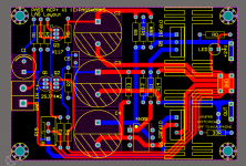
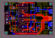
Or if your are comfortable working with Veroboard, you could build something like I have shown here.Sounds like it’s time to learn PCB layout!
Breaking out what you suggest would be very straightforward...
I haven't verified the current source settings around the J113, and have used FQP3N30 output devices instead of the IRFP610. Note that the Mosfets are oriented opposite from one another. This is for the more intrepid amp builder for sure, but should be fun.
Attachments
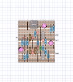
Or if your are comfortable working with Veroboard, you could build something like I have shown here.
I haven't verified the current source settings around the J113, and have used FQP3N30 output devices instead of the IRFP610. Note that the Mosfets are oriented opposite from one another. This is for the more intrepid amp builder for sure, but should be fun.
That looks super cool and fun to boot. Might be a good idea as a trial build to see if I like the circuit. Then transfer over to a fully designed PCB, etc...
Fun!
Thanks,
Anand.
- Home
- Amplifiers
- Pass Labs
- Amp Camp Pre+Headphone Amp - ACP+