Nice
Fulfills three audiophile wishes:
1.Has the right amount of H2 (so, no need for H2 generator)
2. It is a hi-end headphone amp
3. And, can also serve as 1 Watt amp")
Hello Vix.
I have Grado Labs's Model SR 80 headphones [$99 many moons ago] which are 32 Ohms/phone. Using the scope, I find that music signals of amplitude equal to 100 mV peak to peak is plenty drive for my comfortable and extended listening. Thus, the amp's required output current calculates to 0.0011 A (rms). And the power dissipated in each phone is [0.0011A X 0.0011A X 32 Ohms X 1000= 0.039 milli Watts.
H2 negative phase [H2np] is very small at this power level per the graph showing distortion versus output power [in milliwatts]. I do not know how to translate the 1% [H2np] which is suggested by Mr. Pass for/in high power amplification to that at this earphone level. The very low distortion of this amp driving my Grado's operates in a state like that of STASIS; meaning at a constant voltage across and a constant current through the amplifying devices.This amp is accurate.
Best
Anton
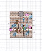
Photos of the not-quite-final BAF'19 Workshop PCB, but close enough that it's fine for illustration.
Looks Great!
Fantasic! Thank you Papa (and Jim)
+1 👏🏻
You'll need extremely efficient speakers (like Nelson's 99dB Tannoys) to actually get away with using it as an integrated amp. Remember that it's being powered by a 500mA wall wart! Those people so inclined will be able to take the output from the headphone jack or the line out RCA jacks.
Including speaker jacks would lead to many people trying it and being disappointed.
Including speaker jacks would lead to many people trying it and being disappointed.
I'd say distortion spectrum would be quite similar but phase of H2 will be positive.... I guess a reversed polarity version with 2SK170s and IRF9610s or FQP3P20 would similar distortion spectrum ?...
Just for fun.
Patrick
.
Bless you. That was one of my questions, can the caps be ditched for a + / - version.
Here is a question
Are NOS Harris parts lower distortion than now-available IR version?
I ask because my vintage Aleph 30 has Harris MOSFETs.
Additional question, does matching the MOSFETs bring any value?
Last edited:
P-channel parts from Vishay, International Rectifier and Siliconix (produced with the same process) has some gain nonlinearity. For voltage gain duty, Harris, Intersil, Fairchild, On Semi and Samsung as liscensee of the IR part number or Toshiba, Hitachi, Zetex and Ixys p-channel parts have been preferred. However, the problem does not hurt all that much at follower duty. N-channel parts do not exhibit such problem. Read art_mos_test.pdf for more detail.... Are NOS Harris parts lower distortion than now-available IR version? ...
This is a great little circuit with lots of potential to be scaled up or down. As is my habit, I've done a quick version that might be applied to the input stage of an M2x, giving an extra 6 dB of gain before the Edcor transformer.
The feedback network is reworked to make R5 and R6 39.1k, and R7 becomes 20k. The C5 cap is reduced to 20 pF. I have chosen to use FQP3N30 for the output Mosfets, and adjusted R12 to 4.7 Ohms to reduce the bias current. I plan to shoot for about 50 mA through the output stage, which will be plenty of drive for the Edcor.
I'm sure some values still need to be adjusted. R4 may end up as 110 or 100 Ohms, as necessary to give sufficient current through R15. R11 probably needs to change as well. The Veroboard outline is similar to what I'm already using for a Diamond buffer; that's the only thing constraining the size. Otherwise it could be made larger to have more room.
Attachments
Last edited:
This is a great little circuit with lots of potential to be scaled up or down. As is my habit, I've done a quick version that might be applied to the input stage of an M2x, giving an extra 6 dB of gain before the Edcor transformer.
The feedback network is reworked to make R5 and R6 39.1k, and R7 becomes 20k. The C5 cap is reduced to 20 pF. I have chosen to use FQP3N30 for the output Mosfets, and adjusted R12 to 4.7 Ohms to reduce the bias current. I plan to shoot for about 50 mA through the output stage, which will be plenty of drive for the Edcor.
I'm sure some values still need to be adjusted. R4 may end up as 110 or 100 Ohms, as necessary to give sufficient current through R15. R11 probably needs to change as well. The Veroboard outline is similar to what I'm already using for a Diamond buffer; that's the only thing constraining the size. Otherwise it could be made larger to have more room.
I used some of that proto board along with a ZIF socket to make a fixture for curve tracing. The rig was plagued with leakage current when no part was inserted.
At first I suspected the ZIF socket. It turned out to be the board. An hour with a selection of tiny saws, I cut away two of the spaces between copper tracks isolating three tracks. The leakage went from 50 nA @ 20V before sawing to single digit pA (noise floor) after sawing.
I look at threshold voltage by forcing between 1 and 10nA and measuring Vgs so 50 nA of leakage was not acceptable for me.
- Home
- Amplifiers
- Pass Labs
- Amp Camp Pre+Headphone Amp - ACP+