So it happens with both supplies. It is probably unlikely that both supplies are defective.
You earlier mentioned that it is a 3V rhythmic surge and it is constant. So at the power switch it is cycling between 24.8V and 27.8 V constantly? But at the power supply entry point it is a constant 24.8V?
You earlier mentioned that it is a 3V rhythmic surge and it is constant. So at the power switch it is cycling between 24.8V and 27.8 V constantly? But at the power supply entry point it is a constant 24.8V?
Yes, sort of. I have a steady 24.2 V (actually) at the power supply.
Taking some additional measurements I found this.
-Switch OFF 24.2 V negative leed of C 6-9, and 24.2 V on the positive side of C 7-9
0 V positive lead of C6.
-Switch ON 24.2 V steady at the power supply and all other measurements are surging or cycling from 0 V to 3V
I'm completely new to this and will try an follow any instructions regarding additional testing.
Where precisely did you measure the surging or cycling 0V to 3V?
Did you follow the instructions and measure the voltage across R18 at each channel? It should be about 0.3V.
Did you also measure the voltage at DC1 at each channel? DC1 is located next to R13. Red probe at DC1 and black probe at Ground. Voltage should be about 11V.
https://www.firstwatt.com/pdf/art_acp.pdf
Page 9 has the testing instructions.
There is no C18. Did you mean R18?
Since you are completely new to this, a few things about measurements. Unless noted otherwise voltage measurements should be DC Volts so set the meter to VDC. When measuring across a component, such as a resistor, place a probe on each end of the resistor. When measuring the voltage at a specific point, place the black probe at GND, and the red probe at the specified point.
Now something doesn't seem right about your first voltage measurement at C18. Assuming that was at R18, you had measured the power supply voltage which you had previously measured as 24.2v.
However it is best to start over and get a complete set of measurements.
Please measure:
1. Voltage at power input, probes at V+ and GND.
2. Voltage across R18, probes at each end of R18
2a. Voltage across R20
2b. Voltage across R21
3. Voltage at DC1, probes at DC1 and GND
4. Voltage across R4, probes at each end of R4
5. Voltage across R13
6. Voltage across R15
Please measure both channels.
Hi Ben Mah,
Yes, I did mean R18, sorry.
Using your instructions I found the following:
1. Voltage at power input, probes at V+ and GND = 24.2v
2. Voltage across R18, probes at each end of R18 = 0 - .3v
2a. Voltage across R20 = .050v
2b.Voltage across R21 = .050v
3. Voltage at DC1, probes at DC1 and GND = Rt 0 - .2v Lt 0 - .2v
4. Voltage across R4, probes at each end of R4 = Rt .7v Lt .7v
5. Voltage across R13 = Rt .002 DCV Lt .002v
6. Voltage across R15 = Rt 0 -.3 DCV Lt 0-.3v
Is this what you were looking for?
Hi phorner,
Yes, there is useful information.
Looking at the numbers, the near zero voltage at DC1 and near zero voltage across R13 indicate that practically no current is flowing through Q5, but also the voltage potential is not visible at the source of Q5. If Q5 was functional and no current flowing, there should still be measurable voltage, close to 24V.
It is interesting that you have identical results in both channels. So both channels have the same problem.
I suspect a bad Q5.
There is also an issue with low voltage across R15. You measured -0.3V when it should be about 4.5V. That could be bad JFET or bad Q6.
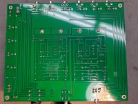
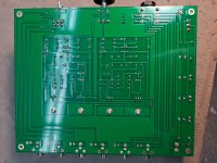
Could you post a picture of the bottom side of the board. I am wondering if there are bad solder joints.
When soldering the components in place, especially the Mosfets (Q5, Q6) and JFETs (Q1, Q2) did you apply heat for a long period of time? I am wondering whether they might have been damaged during soldering.
Yes, there is useful information.
Looking at the numbers, the near zero voltage at DC1 and near zero voltage across R13 indicate that practically no current is flowing through Q5, but also the voltage potential is not visible at the source of Q5. If Q5 was functional and no current flowing, there should still be measurable voltage, close to 24V.
It is interesting that you have identical results in both channels. So both channels have the same problem.
I suspect a bad Q5.
There is also an issue with low voltage across R15. You measured -0.3V when it should be about 4.5V. That could be bad JFET or bad Q6.
Could you post a picture of the bottom side of the board. I am wondering if there are bad solder joints.
When soldering the components in place, especially the Mosfets (Q5, Q6) and JFETs (Q1, Q2) did you apply heat for a long period of time? I am wondering whether they might have been damaged during soldering.
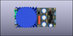
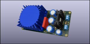
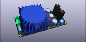
I have been reading through the thread and noticed some people were looking to use linear power supplies to power their ACP+ and so I thought it would be a good time to share an updated design of my original single rail PSU which is called Artemis.
The pics are of a custom version that I was asked to design which is also the basis for my REV B boards. This one is 220V only but the normal version will feature voltage jumpers just like on the Helios Bi-Polar design.
Dimensions are 140mm x 66mm.
Let me know what you think.
The pics are of a custom version that I was asked to design which is also the basis for my REV B boards. This one is 220V only but the normal version will feature voltage jumpers just like on the Helios Bi-Polar design.
Dimensions are 140mm x 66mm.
Let me know what you think.
Attachments
Ben Mah
Ok, I've attached photos of the bottom of the board. I want to say that I did not dwell for long with the heat but...
I'll order Q5, Q6, and JFETs Q1, Q2, and be VERY careful installing them!
Thank you so much for your help with this. I will report back after the new parts have been installed.
Ok, I've attached photos of the bottom of the board. I want to say that I did not dwell for long with the heat but...
I'll order Q5, Q6, and JFETs Q1, Q2, and be VERY careful installing them!
Thank you so much for your help with this. I will report back after the new parts have been installed.
Attachments
Don't replace everything at once. It may be that only the Mosfets are an issue. Issues in one part of the circuit can often adversely affect other parts. The Mosfet section is definitely malfunctioning so address that first. The JFETs are pricey. Don't mess with them yet. Replace the IRF610 first.
What I usually do when I order parts for a project is that I order extras of the transistors and integrated circuits such as the 4N35 optocoupler, especially if they are not expensive, as the IRF610 and 4N35 are both less than $1 apiece. The same goes for the J113. That way I have spares available and don't have to pay for shipping on a small order. The LSJ74 though is a limited supply item so it is expensive. Or you can order them and keep them for a future project if they are not needed for this one.
Looking at the back of your board, and it is hard to tell from the photograph, there are a few areas that look like there are trails of excess solder that may have bridge some traces. You should have a close look at all of the solder joints and check for excess solder bridging to traces. Also doesn't hurt to clean the soldered area with alcohol to remove flux.
Edit:
If you are ordering parts, please order some 1/4W 36 Ohm, 51 Ohm, and 68 Ohm resistors (2 each required) . R4 is not optimal at 125 Ohm so it will need adjusting.
Last edited:
Great advice on all points. Thank you
I'll clean the back of the board as suggested and double-check solder integrity.
Then replace the IRF610 and test.
It's a good idea to order multiples of the transistors and integrated circuits, J113 and optocouplers I'll add some extra LED's too because they keep burning out.
I've built the ACA and Korg B2 without a hitch but feel that I'm gaining some more good practical experience with this project.
Thanks again so much for your time and your help.
I'll post my results after the ordering, shipping, installing and, testing part happens.
Hi people,
I have once asked what I could do about the ACP+ being harsh in the upper frequencies and was asked if I may just listen too loudly and not be used to the flat frequency response all the way up. Now even though this might be true, I have played around with my ACA mono blocks a little and found that if I connect them directly to my Dragonfly, this harshness is NOT present. So now I am asking myself and especially you again: how can this be? So now for me it's clear, that the ACP+ is emphasizing higher frequencies somehow. Could I have made a mistake assembling it? I have all my tools here now and am happy to perform any measurings as long as anyone can guide me as I am a newbie to the DIY biz. Thanks to y'all and have a great day. Stay safe.
I have once asked what I could do about the ACP+ being harsh in the upper frequencies and was asked if I may just listen too loudly and not be used to the flat frequency response all the way up. Now even though this might be true, I have played around with my ACA mono blocks a little and found that if I connect them directly to my Dragonfly, this harshness is NOT present. So now I am asking myself and especially you again: how can this be? So now for me it's clear, that the ACP+ is emphasizing higher frequencies somehow. Could I have made a mistake assembling it? I have all my tools here now and am happy to perform any measurings as long as anyone can guide me as I am a newbie to the DIY biz. Thanks to y'all and have a great day. Stay safe.
Hi people,
I have once asked what I could do about the ACP+ being harsh in the upper frequencies and was asked if I may just listen too loudly and not be used to the flat frequency response all the way up. Now even though this might be true, I have played around with my ACA mono blocks a little and found that if I connect them directly to my Dragonfly, this harshness is NOT present. So now I am asking myself and especially you again: how can this be? So now for me it's clear, that the ACP+ is emphasizing higher frequencies somehow. Could I have made a mistake assembling it? I have all my tools here now and am happy to perform any measurings as long as anyone can guide me as I am a newbie to the DIY biz. Thanks to y'all and have a great day. Stay safe.
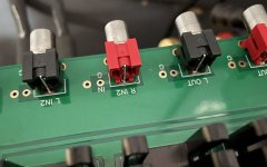
Could you provide a larger image of your build? I went back and found the one you shared earlier, but it was way to small to do any zooming.
I don’t see any big issues on the board, though I’m no expert. Seems you went with an alternative way of mounting the RCA jacks. Might be worth verifying they’re hooked up correctly. For instance, a few of the ‘G’s’ (ground) in the silkscreen were inadvertently bumped down when the artwork was sent off (or at least I assume that was the case).
Hi people,
I have once asked what I could do about the ACP+ being harsh in the upper frequencies and was asked if I may just listen too loudly and not be used to the flat frequency response all the way up. Now even though this might be true, I have played around with my ACA mono blocks a little and found that if I connect them directly to my Dragonfly, this harshness is NOT present. So now I am asking myself and especially you again: how can this be? So now for me it's clear, that the ACP+ is emphasizing higher frequencies somehow. Could I have made a mistake assembling it? I have all my tools here now and am happy to perform any measurings as long as anyone can guide me as I am a newbie to the DIY biz. Thanks to y'all and have a great day. Stay safe.
I notice that you seem to be using Nichicon “Gold” caps for both input and output coupling duties. I did the same, and had the same issue. Swapping the input cap for an Elna Silmic II solved this issue for me, though it’s a tad too smooth for my liking now. I’ll have to see how the sound changes as the cap burns in. Not that I believed in capacitors changing the sound or capacitor burning in until now, but I guess I was wrong.
- Home
- Amplifiers
- Pass Labs
- Amp Camp Pre+Headphone Amp - ACP+