
Power supply
Having just resurrected my ACA from its 8 year rest in a box in the attic and wondering why I put it away it sounds so good driving a pair of Castle Richmond mk1 speakers I’ve just ordered the boards for the ACP and am gathering parts. Do I need a 24v power supply with the centre pin positive if I use the pcb female power connector?
Thx Mike
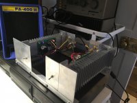
Attached is a pic of the ACA
Having just resurrected my ACA from its 8 year rest in a box in the attic and wondering why I put it away it sounds so good driving a pair of Castle Richmond mk1 speakers I’ve just ordered the boards for the ACP and am gathering parts. Do I need a 24v power supply with the centre pin positive if I use the pcb female power connector?
Thx Mike
Attached is a pic of the ACA
Attachments
I'm building my second ACP+ to use as a preamp (first was headphone amp).
The right channel works fine but the left channel has not output. Here are some voltages:
Q5 - Gate = 23 L - 16 R (working channel)
Q5 - Drain = 23 L - 23 R
Q5 - Source = 19 L - 12 R
Q6 - Gate = 4.0 L - 4.6 R
Q6 - Drain = 19 L - 10.6 R
Q6 - Source = 2.5mV L - 2.5mV R
Attached is a photo. I've looked carefully but can't see any component installed incorrectly and I don't see any bad solder joints, but I could be missing the forest for the trees...
Any suggestions of what to check would be appreciated. I'm sure it's stupid error.
Besides the suggestions from 6L6, I noticed that you have different C3s on each channel but I cannot see their values. They do appear to be in the right polarity, so unlikely the cause but why did you use different types?
Having just resurrected my ACA from its 8 year rest in a box in the attic and wondering why I put it away it sounds so good driving a pair of Castle Richmond mk1 speakers I’ve just ordered the boards for the ACP and am gathering parts. Do I need a 24v power supply with the centre pin positive if I use the pcb female power connector?
Thx Mike
Answering my own question looking at the data sheet for the recommended supply it is centre pin positive.
Attached is a pic of the ACA
Hi there!
I am just getting started in DIY audio and have just received my first Nelson Pass designed amp - ACA 1.6 (prebuilt). Now I will make myself a second one to use them in bridged mono mode. What's missing until now is an appropriate preamp. Was looking to build the ACP+, couldn't find a build guide for it though. Then I saw the guide for the Korg Nutube B1. Can anyone tell what the difference is between the two as they seem pretty similar? Is there gonna be a guide for the ACP+ soonish? Thanks!
I am just getting started in DIY audio and have just received my first Nelson Pass designed amp - ACA 1.6 (prebuilt). Now I will make myself a second one to use them in bridged mono mode. What's missing until now is an appropriate preamp. Was looking to build the ACP+, couldn't find a build guide for it though. Then I saw the guide for the Korg Nutube B1. Can anyone tell what the difference is between the two as they seem pretty similar? Is there gonna be a guide for the ACP+ soonish? Thanks!
Hello again folks!
Can somebody recommend a good power supply for the ACP+ which is available in Germany? At Mouser I did find the XP Power "VER24US240-JA" and the "VET24US240C2-JA", on Amazon the "KFD Trafo Steckernetzteil 24V 1A Netzteil 5,5 2,1mm 0,6a 400ma and have no idea for which to go. Tending towards XP Power only because Mouser sells it. Also to complete my order I need information about specifications of these 4 items:
1) 4 Standoff nuts
2) 1 Standoff
3) 4 PCB Base
4) Mosfet mounts
Could someone point articles out to me on Mouser if possible? I don_t know what I am exactly looking for and don't wanna order the wrong stuff. That'd be great!
Thanks in advance.
Hi....if you look in the very first post on this thread you will see a link from Nelson Pass to the First Watt site where there is a basic guide with a parts list including the hardware specs. The power supply mentioned is 24v 500ma centre pin positive so any matching that spec should work. Ahhh Dirk beat me to it :0)
Mike
Mike
Yes I read Nelson's article on the ACP+.
I know all of the power supplies will work but I thought maybe one of you might have experience with a manufacturer so I don't buy poor quality.
I mixed up some parts of Nelson's list, so I think I am all good now. Hopefully! Will be really annoying when all the parts arrive and I forgot something")
Thanks!
I know all of the power supplies will work but I thought maybe one of you might have experience with a manufacturer so I don't buy poor quality.
I mixed up some parts of Nelson's list, so I think I am all good now. Hopefully! Will be really annoying when all the parts arrive and I forgot something
Thanks!
The RK27 series fits the PCB -
ALPS potentiometers | HiFi Sono DIY | Audiophonics - Audiophonics
Get the 10K, 20K, or 50K
Potentiometer ALPS stereo RK27 high quality 10 Kohm - Audiophonics
ALPS potentiometers | HiFi Sono DIY | Audiophonics - Audiophonics
Get the 10K, 20K, or 50K
Potentiometer ALPS stereo RK27 high quality 10 Kohm - Audiophonics
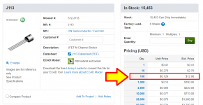
Hey everyone. I just received my parts for my ACP today and decided to test and match J113's while I wait on the boards.
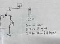
I made myself a small testing breadboard with 125 ohm resistor, 12V battery, and measured across the resistor for 1.25V. Unfortunately, the design I am trying fried two JFETs.
The picture shown is the same schematic in Post #491 and I wrote out where each leg on the JFET "should" go in the schematic. Anyone see something wrong with how I wrote this up and the orientation of the legs of the JFET?
Attachments
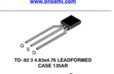
This is where I got it from:
https://www.mouser.com/datasheet/2/149/J113-889353.pdf
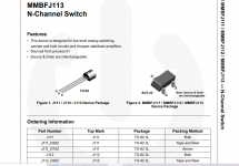
Looking at the schematic, the gate of Q3 (J113) is connected to the source of Q1 and Q2. Looking at the pcb, which shows the orientation of Q3 (J113), it appears that the J113 pin orientation agrees with the pin orientation shown in the data sheet that I referenced.
https://www.mouser.com/datasheet/2/149/J113-889353.pdf
Looking at the schematic, the gate of Q3 (J113) is connected to the source of Q1 and Q2. Looking at the pcb, which shows the orientation of Q3 (J113), it appears that the J113 pin orientation agrees with the pin orientation shown in the data sheet that I referenced.
Last edited:
- Home
- Amplifiers
- Pass Labs
- Amp Camp Pre+Headphone Amp - ACP+