Is it too much to project that this could put out 2-3 watts @ 3 percent distortion figure? NP's distortion vs. power graph looks like it doesn't have much of an elbow out to 1 watt.
That would put power into the realm of 45 or 2A3 type tubes as far as efficiency requirements are concerned.
That would put power into the realm of 45 or 2A3 type tubes as far as efficiency requirements are concerned.
It could certainly be scaled up, but that is a lot more work than the simple scale down that I did. A pair of IRFP240 Fets in the output stage, 0.22 Ω resistance up, 0.68 Ω resistance down (with parallel resistors), feeding a 3300 uF or 4700 uF output cap. Feedback network same as Pa showed originally, or tweaked for a touch more gain. Too much to do on Veroboard, but the basic concepts apply.
You would end up with something similar to an ACA, which already has a nice PCB available from the store.
You would end up with something similar to an ACA, which already has a nice PCB available from the store.
Last edited:
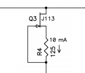
How is the J113 selected for the CCS of the input stage?
When I read the datasheet J113 has a min. Idss = 2.0 mA. Those can't be used as a 10 mA CCS? …..you need one with a bit higher than 10 mA Idss? …..are there many of those among J113 in a batch?
J112 has min. Idss = 5.0 mA so some of those could also be used?
When I read the datasheet J113 has a min. Idss = 2.0 mA. Those can't be used as a 10 mA CCS? …..you need one with a bit higher than 10 mA Idss? …..are there many of those among J113 in a batch?
J112 has min. Idss = 5.0 mA so some of those could also be used?
.......
.......if you're doing your own pcb
.........
then you can make dumbest possible CCS with parts from Grocery Store
Pa is having his own Grocery Store , choosing accordingly
for this project , choices are his own ,logically
How is the J113 selected for the CCS of the input stage?
When I read the datasheet J113 has a min. Idss = 2.0 mA. Those can't be used as a 10 mA CCS? …..you need one with a bit higher than 10 mA Idss? …..are there many of those among J113 in a batch?
J112 has min. Idss = 5.0 mA so some of those could also be used?
Use J111 or whatever jfet that will do the job.
J111 has Idss of 20mA then you degenerate with source resistance to get 10mA.
Papa is using 125 ohms to degenerate.
Last edited:
what's wrong with ringoftwo?
with parts collected from floor by workbench?
Nothing wrong with skinning cat in different ways.
https://pdfs.semanticscholar.org/204a/38f2d10afc4c05f56009a8997120126e981a.pdf
Somewhere there's a nice graphic someone did of current sources as a pretty neat summary of pro's/cons
Edit Constant Current Source (CCS) For Audio Applications
Somewhere there's a nice graphic someone did of current sources as a pretty neat summary of pro's/cons
Edit Constant Current Source (CCS) For Audio Applications
Attachments
Last edited:
It’s probably worth pointing out that psrr performance of the jfet ccs is not super critical in this particular location.
1) We have a regulated switch mode power supply.
2) We have RCRCRC filtering after the regulator
3) Then we have RC filtering (R8, C2) on the rail feeding the Jet CCS
1) We have a regulated switch mode power supply.
2) We have RCRCRC filtering after the regulator
3) Then we have RC filtering (R8, C2) on the rail feeding the Jet CCS
And the Tannoys are 95 dB.
Here's a dumb question if the circuit produces 1 watt at 32ohms how many watts will it produce for an 8ohm load? I'm definitely going to try it out with my old Fortes. It would be nice if i could get the circuit to produce 1 watt driving an 8ohm speaker, then I could test the actual sensitivity of my speakers. I have a dB meter after all. If the test goes well i could always put the old crossovers back in and compare.
Here's a dumb question if the circuit produces 1 watt at 32ohms how many watts will it produce for an 8ohm load? I'm definitely going to try it out with my old Fortes. It would be nice if i could get the circuit to produce 1 watt driving an 8ohm speaker, then I could test the actual sensitivity of my speakers. I have a dB meter after all. If the test goes well i could always put the old crossovers back in and compare.
Have you considered ACA?
Output stage is essentially the same as this but biased at an appropriate level for speakers.
This circuit is very much limited by the bias current.
I’m guessing your speakers don’t produce a nice 8 ohm impedance plot.
You would need to increase the bias to achieve 1 watt rms into 8 Ohms which would then most likely need larger heat sinks than those shown.
Last edited:
Thank you for the suggestion. I have those in the stash/horde. Just ordered a quad of LSJ74 from the store.> Are NOS Harris parts lower distortion than now-available IR version?
For TO220, just use FQP3N30 / FQP3P20.
Then no need to worry.
Patrick

For those who are unwilling or unable to buy a handful of J113s, and make the necessary measurements to choose the right resistor values which create two 10mA current sources ...
I'm curious to know: how much would you pay "punkydawgs" or "fetaudio" another seller, to do the work for you? You pay him money and he sends you two little ziptop envelopes, each envelope contains 1 JFET and 1 resistor. Each envelope creates a 10.0 mA (± 5%) current source?
thanks
_
I'm curious to know: how much would you pay "punkydawgs" or "fetaudio" another seller, to do the work for you? You pay him money and he sends you two little ziptop envelopes, each envelope contains 1 JFET and 1 resistor. Each envelope creates a 10.0 mA (± 5%) current source?
thanks
_
Attachments
- Home
- Amplifiers
- Pass Labs
- Amp Camp Pre+Headphone Amp - ACP+