A couple more questions: I've put Vishay-Dale CMF resistors in my Mouser cart for all the 1/2w resistors, except R12 and R13. It seems those values (2.2R and 6.8R) aren't available in the CMF series, nor in the RN series.
Any suggestions as a replacement? I see some Panasonic ERX series are available in 2.2R and 6.8R, but they're 1W and probably won't fit the board lying flat. They would match the ERXs I have picked out for the 3W resistors though. Rrrr, sometimes I wish I wasn't so OCD
Any reason not to parallel a couple of CMF50s to get close to 2.2R and 6.8R ?
Next, does the brand/variation of the Optocoupler matter? I'm seeing variance between the different options in If(Forward Current) Isolation Voltage (3550V, 5000V, 7500V - probably doesn't matter?) and Power Dissipation (70, 150, 250 & 350mW).
If it makes any difference, I'm planning on building with the thru-hole PCB as sold in the DIYAudio store.
Thanks,
Kevin
Last edited:
I have the same question. I've seen it asked a couple times on this thread, but haven't seen an answer yet.
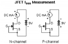
During our project we followed the matching instructions here for the J113s:
JFET matching information – diyAudio Store
And picked up a matched quad of LSJ74s from the store.
Wasn't really prepared for the J113 matching and only ordered 2! They were a match
. All said, we still used 125R R4s per Nelson's guide. Wasn't simple (to me) to verify the 10mA noted on the schematicRight or wrong with any of it, we ended up with a build that measured correctly, based on NP's paper and instructions, at points DC1.
(And thanks to you fine peeps that enjoyed the father daughter time build and commented as such!)
It's a great sounding pre. We recently used it outside, naked style, for outdoor movies in front of Mark's Cordell gainclone. Super good! And LOUD!
Last edited:
Ok, another: I assume C5 is a ceramic cap, right? Does the dielectric type or any other specs matter? Anyone have a favorite brand/series of this type of cap to help me narrow down my options? Preferably one that's available on Mouser.
I think Murata or TDK would be fine. Probably anything really. Might be able to find polypropylene.
As for the alternate resistors, I’d look for Vishay/Beyschlag 0207 types.
Edit: Check out Wima FKP2O100331D00KSSD for the 33pf cap
Last edited:
We weren't able to find the "gold" caps in the right spacing—out of stock most places at the time—picked up some that were 7mm and bent the legs under and in. They sit flush to the PCB due to the insulation pad on the bottom. FWIW. Worked great.
Also—here's a PN for a PC mount power switch (Mouser: 612-100-A1421):
https://www.mouser.com/ProductDetai...bEwqjve6twN2uKtQlAFlb9yVBMH77SOq3/zpvKuZcEg==
Also—here's a PN for a PC mount power switch (Mouser: 612-100-A1421):
https://www.mouser.com/ProductDetai...bEwqjve6twN2uKtQlAFlb9yVBMH77SOq3/zpvKuZcEg==
Wasn't really prepared for the J113 matching and only ordered 2! They were a match
How did you verify those 10 mA? I have a bunch of J113 and want to do the same.
Couldn't "verify" the 10mA, my understanding is that to actually take that measurement you need to lift an R4 leg while in circuit. Based on the link above I posted with instructions for testing Jfets—it indicates that 1V = 10mA, while that might be accurate, I understand it's different in circuit—maybe someone who knows more can weigh in with details. Our J113s measured 1.68 and 1.66VDC under the test conditions in the instructions.
Thank you. Got it.
Next question: Is it possible to measure it before inserting into the circuit?
The range of J113 Idss is quite wide..
Building this little circuit on a breadboard, will this be ok when I measure 10 ma here? Here I can choose the FET or resistor as i like without damaging the PCB...
Thanks,
Ulf
Next question: Is it possible to measure it before inserting into the circuit?
The range of J113 Idss is quite wide..
Building this little circuit on a breadboard, will this be ok when I measure 10 ma here? Here I can choose the FET or resistor as i like without damaging the PCB...
Thanks,
Ulf
Attachments
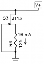
If, like me, you still don't have a breadboard or lab PS, is there anything wrong with dialing in 10mA thru R4 by temporarily using a trimpot in place of the R4 resistor, then replacing the trimpot with a standard fixed resistor once the ideal value of R4 is determined?
That is a very appropriate thing to do.
- Home
- Amplifiers
- Pass Labs
- Amp Camp Pre+Headphone Amp - ACP+