
good day mates, im not part of the down under gorp for the H2. I just received mine at Burning Amp in SF and this was the only tread I was pointed to in the search ( H2 preamp). I found the article on the H2 at FIRST WATT http://www.firstwatt.com/pdf/art_h2_v1.pdf
My question should there only be two J112 or four J112, my package only had two.
had the LM317 for Q3
in the schematic on First Watt Q1 Q2 but it gives no part number. Q1 and Q2 are both the same J112 will total 4 Jfets. For the resistors all values listed.
it looks easy to get and cheap at mouser J112 ON Semiconductor / Fairchild | Mouser
I read the J112 Vp number was important for matching I suppose. The number that was written on the plastic bag. Mine was either 18.5 or 2.81 depends how you try to read the hand writing and flip the bag.
I never did any matching before but I guess it is time to learn. Can someone kindly send me a link how to match the Vp on this type Jfet.
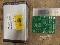
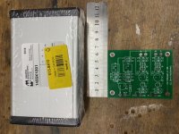
Our packages had 2 Fets in a separate smaller bag marked at around 2.6 to 2.8 Vp (mine here are 2.78) and the 2 off LM317LZ's in the TO92 package (not the usual TO220 style). Yours marked at 2.81 is the correct number (not 18.5) . You only need 2 JFets but the pcb has 2 options with different pin outs to suit different Fet options - so make sure you solder the J112's in the correct position
A quick email to NP should sort out your other questions on matching
Nelson has mentioned how to measure Vp - look in the normal H2 thread at a guess.
Gary..
A quick email to NP should sort out your other questions on matching
Nelson has mentioned how to measure Vp - look in the normal H2 thread at a guess.
Gary..
Last edited:
good day mates, im not part of the down under gorp for the H2. I just received mine at Burning Amp in SF and this was the only tread I was pointed to in the search ( H2 preamp). I found the article on the H2 at FIRST WATT http://www.firstwatt.com/pdf/art_h2_v1.pdf
The main thread is here and if the latest video with NP from BAF 2019 is online as well now in case you missed it being there.
H2
Our packages had 2 Fets in a separate smaller bag marked at around 2.6 to 2.8 Vp (mine here are 2.78) and the 2 off LM317LZ's in the TO92 package (not the usual TO220 style). Yours marked at 2.81 is the correct number (not 18.5) . You only need 2 JFets but the pcb has 2 options with different pin outs to suit different Fet options - so make sure you solder the J112's in the correct position
A quick email to NP should sort out your other questions on matching
Nelson has mentioned how to measure Vp - look in the normal H2 thread at a guess.
Gary..
What gary s said.
Plus from the H2 article over at FW (cf. p.6):
So, don't get your Q1/Q2 mixed up with your Q3/Q4.The J112 Jfet (Q1/Q2) has been chosen as a suitably cheap choice and carefully matched out of a population with a 2.5V to 3.0V pinch-off voltage and an Idss of 30+ mA. In this circuit this Jfet itself has a voltage gain of about 14 dB, and could easily serve as a preamp with a volume control and such.
...
The power supply is a regulated 24V DC wall wart rated at 0.5A. Yes, the regulator is a “crummy” LM317 (Q3/Q4). A bit noisy, but in this version I added some passive filtering after the regulator that takes care of that.
Here's a nice article on jfets, with examples on measurement:
JFETs: The New Frontier, Part 1 | audioXpress
JFETs: The New Frontier, Part 1 | audioXpress
Thanks everyone, all the info I needed. And I will learn a little more with the extra reading.
PS: by the way was the selection of the resistors on purpose and masterfully combined or was that just coincidence 3.32k, 33.2k, 332, 33.2 I think Papa has a sense of humor and did this intentionally to play with people with bad eyes, people who try to do their projects late at night when they’re tired and brains not working, newbies who do not know how to read their volt meters, People who cannot read color bands. I made two mistakes very late at night with tired eyes had to stop and walk away from the project and come back the next day to find the mistake.
By the way two of my resistors color bands were ( yellow yellow red gold brown =42.2 but measured 32.2 which is correct and what it should be.

Hi Marty, as NP still works in inches I believe, the pcb is 3.25" x 2.5" or in our language 82.5mm x 63.5mm.
Affirmative. I’m going with the 75mm wide Hammond case pictured. I’ll be trimming ~8mm off the end with the print to be able to slide it in. I’m also putting a 50k Alps blue pot on the input.
Attachments
No matter what you are building or how simple or complex the circuit might be, it does definitely pay to measure all resistors with a DMM, to check they are OK and are within the tolerance range or indeed are not incorrectly marked with the colour bands - this has happened before, so I strongly agree with Nelson's point in his post.
Roo2, it is also nice to see those Hammond enclosures are still made in Canada and not China!
Roo2, it is also nice to see those Hammond enclosures are still made in Canada and not China!
Affirmative. I’m going with the 75mm wide Hammond case pictured. I’ll be trimming ~8mm off the end with the print to be able to slide it in. I’m also putting a 50k Alps blue pot on the input.
I've got the slightly longer one of those sitting idle, so good to know it will fit in width-wise.
... it does definitely pay to measure all resistors with a DMM, to check they are OK and are within the tolerance range or indeed are not incorrectly marked with the colour bands - this has happened before, so I strongly agree with Nelson's point in his post.
Definitely a good idea. I've got a stash of 1% to choose from as I tend to go for the bulk discounts when placing an order.
I have found Chinese made resistors with 1% tolerance often outside +/- 1% in the past. But, they are cheap.
I use Dale now from Mouser and have not had one measure incorrectly in the last few years - basically you get what you pay for today.
Dale or Takman are great.
Last edited:
Got mine this arvo, when I got home from work.
Thanks for the smile
 , havn't heard "arvo" for while... might even make me smile at brekkie tomorrow morning .... you crazy ozzies
- Status
- This old topic is closed. If you want to reopen this topic, contact a moderator using the "Report Post" button.
- Home
- Amplifiers
- Pass Labs
- Pass H2 kits for Australia and New Zealand.