")
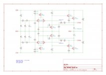
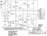
Holy cow. The regulator circuit in the PDF ZenMod posted is the same topology as the Naim NAP250 regulator by Julian Vereker:
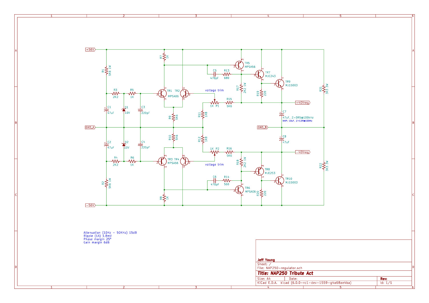
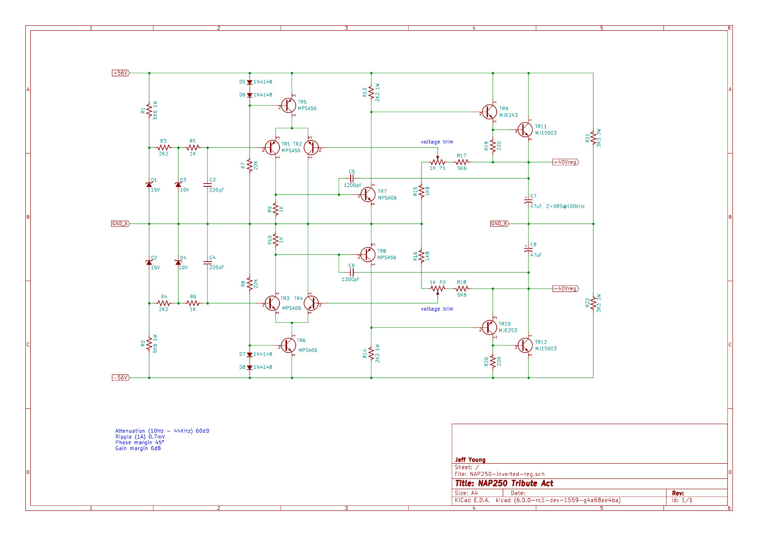
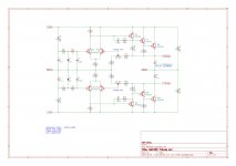
It has horrible PSRR at higher frequencies, mainly because the VAS are referenced to the +/- rails and there's no CCS on the LTP. I was going to "fix" it by inverting the VAS (referencing ground), which also requires inverting the LTP, and then add a really simple CCS:
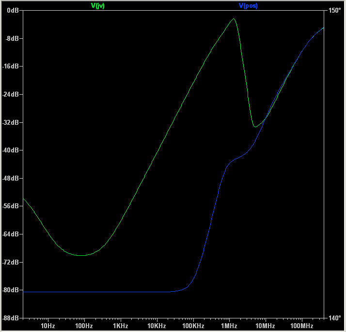
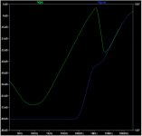
Attenuation of JV's regulator (green) and my inverted one (blue):
However, now I'm wondering. If it's good enough for Threshold, what am I missing?
Cheers,
Jeff.
It has horrible PSRR at higher frequencies, mainly because the VAS are referenced to the +/- rails and there's no CCS on the LTP. I was going to "fix" it by inverting the VAS (referencing ground), which also requires inverting the LTP, and then add a really simple CCS:
Attenuation of JV's regulator (green) and my inverted one (blue):
However, now I'm wondering. If it's good enough for Threshold, what am I missing?
Cheers,
Jeff.
Attachments
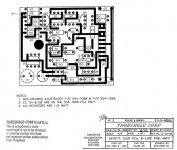
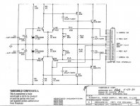
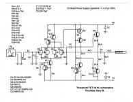
The power supply schematic is for the powers supply circuit inside the main FET 10e HL chassis. The remote power supply has just a torroid transformer, two electrolytic capacitors, a diode bridge, resistor and LED.
I never needed a schematic for the remote power supply since it is so simple.
I never needed a schematic for the remote power supply since it is so simple.
- Status
- This old topic is closed. If you want to reopen this topic, contact a moderator using the "Report Post" button.
- Home
- Amplifiers
- Pass Labs
- Threshold fet ten/e high level