Zen,
there is no c5, c6. (capacitor)
maybe you mean header 5 and 6 ?
if you menth, header 5 and 6,
those are the measuring points for the IQ. (IQL1 and IQR1)
measuring not referenced to ground but between the 2 pins (1 header)
like you stated in your blog,
all measurements are made with inputs shorted (cinch and xlr). no speaker attached.
the absolute voltage is measured between ground and the (red or black) speaker terminal.
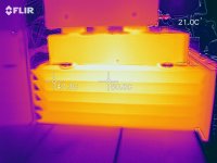
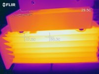
now, after 3,5 hours, playing very low volume, the temperature is risen to:
left 51.2 and right 50.3 degrees c. (ambient = 22)
there is no c5, c6. (capacitor)
maybe you mean header 5 and 6 ?
if you menth, header 5 and 6,
those are the measuring points for the IQ. (IQL1 and IQR1)
measuring not referenced to ground but between the 2 pins (1 header)
like you stated in your blog,
all measurements are made with inputs shorted (cinch and xlr). no speaker attached.
the absolute voltage is measured between ground and the (red or black) speaker terminal.
now, after 3,5 hours, playing very low volume, the temperature is risen to:
left 51.2 and right 50.3 degrees c. (ambient = 22)
Last edited:
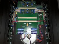
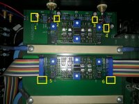
gimme full picture showing main board and I'll show which caps are C6 and C7 (there are four big horizontal electrolytics on pcb , near connection block)
if there is symmetrical voltage at them ( and it will hardly be anything other) , you'll need new UGS modules , as Wayne sez
if there is symmetrical voltage at them ( and it will hardly be anything other) , you'll need new UGS modules , as Wayne sez

Maybe a stupid question...
The measurements are made with inputs groundet.
Rca short, clear.
Xlr short,... the standard amp's u short between 1 and 3 ?
That is only grounding the negative input. ( is what i did).
Should i have shorted pins 2 and 3 maybe ? (Positive and negative pins)
The measurements are made with inputs groundet.
Rca short, clear.
Xlr short,... the standard amp's u short between 1 and 3 ?
That is only grounding the negative input. ( is what i did).
Should i have shorted pins 2 and 3 maybe ? (Positive and negative pins)
The modules can be had from the factory. Kent would let you know what the
cost might be (his job description is Customer's Best Friend).
kente@passlabs.com
I would also ask him for referral to a good technician in Europe.
cost might be (his job description is Customer's Best Friend).
kente@passlabs.com
I would also ask him for referral to a good technician in Europe.
Hi,
back with news.
the UGS4 module is not available anymore.

the UGS6 module is an alternative replacement but is not a 1:1 replacement and needs tweaking by a dealer ( in my case , the nearest is the netherlands )
about the question of the dc voltage on the C6 and C7, those are both 43.5 Vdc.
the C13 and C14 are both 46Vdc.
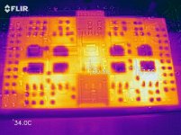
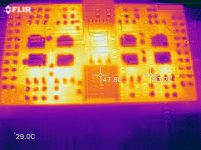
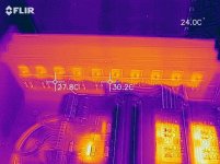
made some pictures...
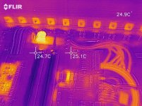
all heat sink fets seams okay to me. even the resistors seames okay.
it is clear that the UGS4 module of the left channel (top pcb) has more heat dissipation on 1 transistor (or the resistors aside).
this is due to the close up pic and 2 cameras (flir) giving somewhat shifted pictures. (outlining of components vs IR view.)
pictures says more...
greetz from Belgium.
back with news.
the UGS4 module is not available anymore.
the UGS6 module is an alternative replacement but is not a 1:1 replacement and needs tweaking by a dealer ( in my case , the nearest is the netherlands )
about the question of the dc voltage on the C6 and C7, those are both 43.5 Vdc.
the C13 and C14 are both 46Vdc.
made some pictures...
all heat sink fets seams okay to me. even the resistors seames okay.
it is clear that the UGS4 module of the left channel (top pcb) has more heat dissipation on 1 transistor (or the resistors aside).
this is due to the close up pic and 2 cameras (flir) giving somewhat shifted pictures. (outlining of components vs IR view.)
pictures says more...
greetz from Belgium.
Attachments
Last edited:
because i don't have the tools for desoldering smd's nor the schematic, nor the right spare fet's and i dont want to ruine those UGS4's.
the official repair is too expensive…
want to keep this amp because it sounds wonderful !
afraid to open up too much the trottle , avoiding eventual clipping and damaging my loudspeakers.
17 vdc left and 5 vdc right of absolute potential is too much...
the official repair is too expensive…
want to keep this amp because it sounds wonderful !
afraid to open up too much the trottle , avoiding eventual clipping and damaging my loudspeakers.
17 vdc left and 5 vdc right of absolute potential is too much...
the UGS4 module is not available anymore.
It's my opinion that a new or repaired UGS would need some adjustment
in any case.
I would go with the UGS 6 (a pair) and have one of the qualified techs we
know in Europe adjust them.
Of course your fallback is sending it to California.
- Status
- This old topic is closed. If you want to reopen this topic, contact a moderator using the "Report Post" button.
- Home
- Amplifiers
- Pass Labs
- Ask help on PASS X150 dc output differential settings