Here are some docs that may have gotten lost in the GB thread with all the list updates.
The BOM is for a single channel, so you'll need double of everything.
The LTP current document is my attempt to find the "sweet spot" for the LTP current. I make absolutely no claims to its correctness -- it represents the bleeding edge of my skill level.")
The BOM is for a single channel, so you'll need double of everything.
The LTP current document is my attempt to find the "sweet spot" for the LTP current. I make absolutely no claims to its correctness -- it represents the bleeding edge of my skill level.
Attachments
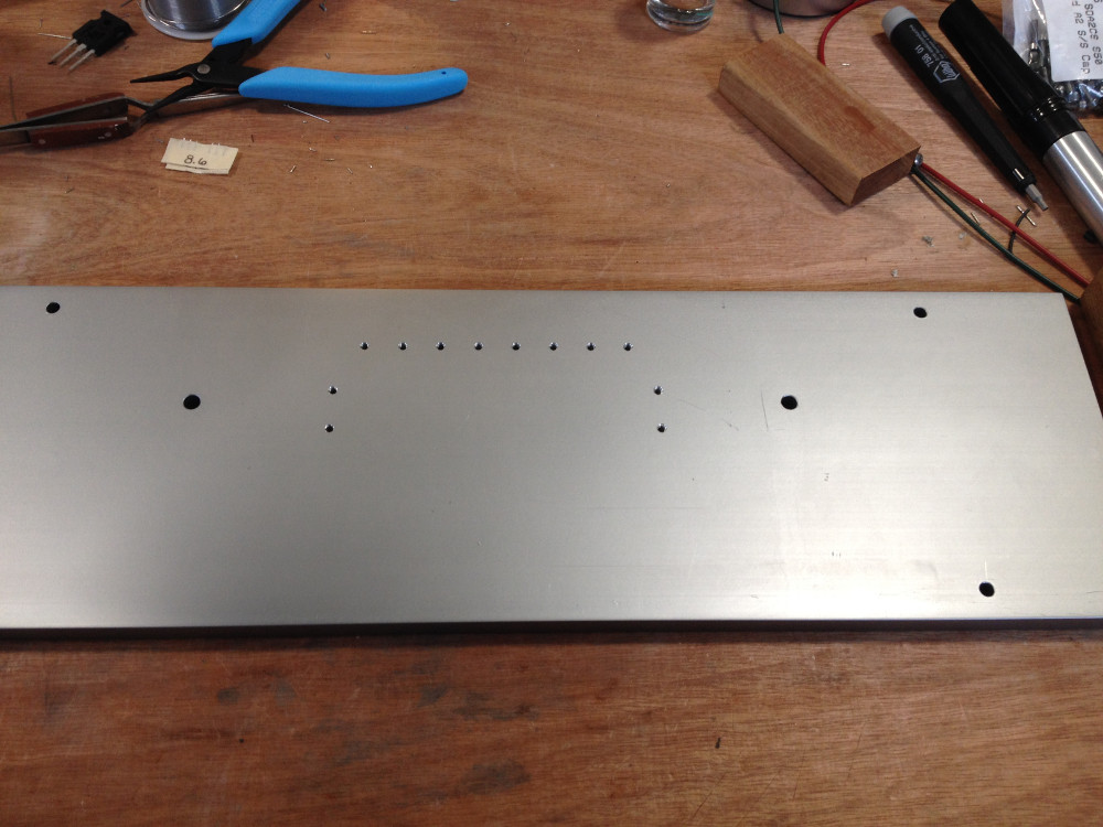
For those of you using an enclosure from Thailand, it would seem their imperial-to-metric conversions are somewhat challenged. They appear to have come up with 50.4mm for 2" (instead of 50.8mm). No big deal for a pair of holes, but by the time you get to 6 you've accumulated 2mm of error.
The holes are a bit oversized so if you centre the middle two holes then you'll just need to elongate the far outside holes by about 0.8mm (towards the centre of the board). Don't worry about filing through the copper, there are no connections to the pads around the holes.
For those making their own 'T' or 'L' sections, the hole spacing of the boards is 2" or 50.8mm.
Front plate drilled and tapped for diodes:
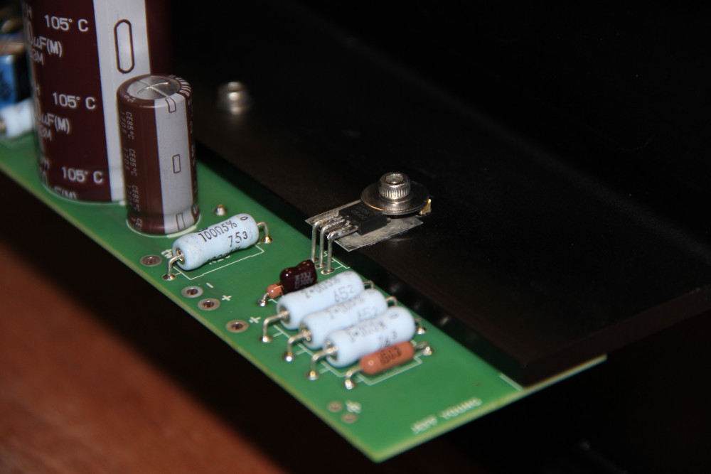
Heatsink prepped (FET footprints polished and brass fulcrums installed for the power resistors):
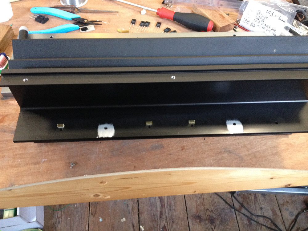
Note that it appears that the Ohmite leads are long enough to mount the resistors directly in the holes, but I used the fulcrum method on my F3 (the Lovoltechs don't have holes at all) so I'm sticking with it.
Heatsink prepped (FET footprints polished and brass fulcrums installed for the power resistors):
Note that it appears that the Ohmite leads are long enough to mount the resistors directly in the holes, but I used the fulcrum method on my F3 (the Lovoltechs don't have holes at all) so I'm sticking with it.
Attachments


Pass DIY Addict
Joined 2000
Paid Member
I found a stash of 2SJ109s a year or two ago in a HAM radio shop that was going out of business. They only had 13, but yes, four of them are going into my J2.
I still haven't decided on the CCS FETs. I have a quad of SemiSouth's from TeaBag's GB, and another quad on the way from Patrick's GB, so I'm leaning toward using a full set in the J2.
And yes, I have an ever-growing backlog too....
I still haven't decided on the CCS FETs. I have a quad of SemiSouth's from TeaBag's GB, and another quad on the way from Patrick's GB, so I'm leaning toward using a full set in the J2.
And yes, I have an ever-growing backlog too....
Will follow this thread with interest as I have a set of pcb's from Jeff, and have the Semisouths, will use the Toshiba 2SK3497 as the CCS, waiting on the 2SK170GR to arrive from the US, have the 2SJ109's (purchased years ago before they were out of production) and getting all other parts together now for a build on this as my next project for early next year.
Just deciding on the chassis to buy and have ordered the toroid.
I like to have all parts ready to go, matched and tested before I start the build, that way it is a seamless and pretty quick process. I have the schematic and BOM all printed out and will do the usual chassis wiring diagram soon. I also print out any tips, tricks and observations for reference as they are posted, together with any photo's that will help with the build.
Running up on the bench supplies.
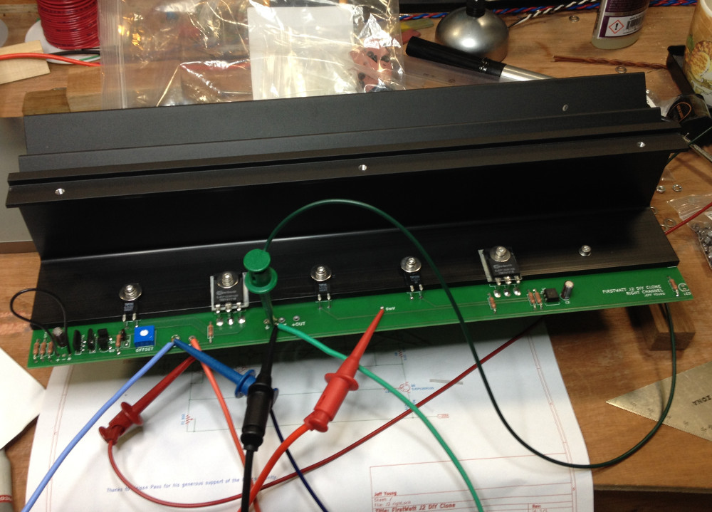
Stabilised at 1.45A bias.
Temps:
2SK170s: 40ºC
2SJ109s: 42ºC
SJEPs: 68ºC
Heatsink next to SJEPs: 57ºC
Heatsink overall: 40ºC
FWIW, the Ohmites followed the overall heatsink temp, suggesting they may not need to be mounted on the heat sink at all.
Stabilised at 1.45A bias.
Temps:
2SK170s: 40ºC
2SJ109s: 42ºC
SJEPs: 68ºC
Heatsink next to SJEPs: 57ºC
Heatsink overall: 40ºC
FWIW, the Ohmites followed the overall heatsink temp, suggesting they may not need to be mounted on the heat sink at all.
Attachments

I used quads, but I'm not sure matching makes that much difference for the J2.
The ratio of Vgs between the CCS and the output device will affect the distortion signature, but I'd guess they'd have to be off by 10% or more to notice. And I don't think there's any requirement to match across channels (other than to have the ratio between the CCS and output device be close to the same).
So if you can get a quad then you don't have to worry about any of the above -- but I'd still build one with singles if that's all I could find.
Cheers,
Jeff.
Ok....will see what I can get.
And the Ohmites are instead of the Panasonic MOX in the original FW J2.....as far I can see from 6moons review…..so since power resistors are used then I would also mount Ohmites on the heatsink or at least use small clip on heatsinks.
6moons audio reviews: FirstWatt J2
The power JFETs used in FW J2 are E120R125.....
Input stage can be used both balanced and SE. If SE then you ground IN- it seems.
The Panasonics in the original are metal film (ERX instead of ERG, although Panasonic's datasheet is confusing as hell). I used the Ohmites just because they looked cool, but it appears from my temp measurements that they don't get hot enough to actually need heat-sinking.
I think Nelson stated somewhere that the FW units used both SJEP120R125s and SJEP120R100s -- or at least that they were interchangeable for our purposes -- I can't remember exactly.
BTW, you can get the little shorting plugs for the balanced input XLR connectors from HifiCollective (Cardas CGSP XLR Shorting Strap | Hifi Collective).
Cheers,
Jeff.
Ok.....thank you…..will see if I actual install XLR or I just strap it on PCB and make til amp SE input only. It will be a "slow" project making it step by step. Will get all the components and mount it on heatsink and then see what I will do with PSU and chassis (stereo or mono blocks etc.). Now I ordered the 2SJ109 (10 pcs….so I might be able to match a little bit) in BL-grade from I think a trusted source. I have some LSK170 in grade A.....maybe I can use those instead of getting 2SK170 in GR grade.
Can the 2SK3497 be used as the CCS transistor without other modification of schematic?
If I am able to get let us say 10 pcs of the expensive SS JFETs…..what is the chance that I have 2 or 4 that can be used for the J2 clone (depending on 2SK3497 use or not)?
Which parameter(s) can be used to match those power JFETs?
We may not call it "a match" but just a parameter so JFETs can be used in the amp?
(Ids at Vgs = 0V is not very interesting for these type of JEFTs).
Instead of the Ohmite my "local dealer" has these Caddock's:
MP915-10.0-1% | Caddock Modstand 10Ω +-1% 15W Power-film MP915 Serien | RS Components
It guess it is "same same"...….
- Home
- Amplifiers
- Pass Labs
- Long skinny builders thread