Double checking posts #322 and #323 - if we have the 4 JFETS pre-populated by you with SMD 2SK2145 in J101-J104 we do NOT populate R110 and R114 is that correct?
t'was an option for Greedy Boyz, to try and decide - more LTP Iq , or not
later I decided that always the same is best
so , no additional resistors (R110 and R114) for higher LTP Iq
as I promised - Eagle generated parts list , BOM , whatever
if in doubt - just take a look at schematic........ and it'll be crystal clear
Rule #1 ... which I missed
New look for 2020, no brown resistors in this one, even the 0R is matching!!!
Felt like it took longer than stuffing SissySIT but at least there are only 2 pots to twist this time instead of 4 (per channel).
On the plan -
IRFP150 up, IRFP150 down to make sure it is working
IRFP150 up, SS 120R100 down to make sure ears are working
IRFP150 up, Cree SiC down


I took pictures to celebrate but it felt like something was missing ... then I realized I didn't take my favorite blue Serbian vitamin. Too bad I only have nice grey vitamin that Wayne suggested. Blue vitamins are for Singing Bush ... one step at a time ...
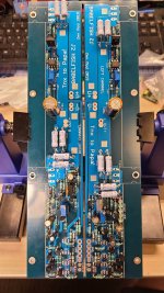
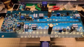
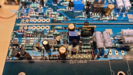
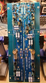
Felt like it took longer than stuffing SissySIT but at least there are only 2 pots to twist this time instead of 4 (per channel).
On the plan -
IRFP150 up, IRFP150 down to make sure it is working
IRFP150 up, SS 120R100 down to make sure ears are working
IRFP150 up, Cree SiC down


I took pictures to celebrate but it felt like something was missing ... then I realized I didn't take my favorite blue Serbian vitamin. Too bad I only have nice grey vitamin that Wayne suggested. Blue vitamins are for Singing Bush ... one step at a time ...


New look for 2020, no brown resistors in this one, even the 0R is matching!!!
Felt like it took longer than stuffing SissySIT but at least there are only 2 pots to twist this time instead of 4 (per channel).
On the plan -
IRFP150 up, IRFP150 down to make sure it is working
IRFP150 up, SS 120R100 down to make sure ears are working
IRFP150 up, Cree SiC down
I took pictures to celebrate but it felt like something was missing ... then I realized I didn't take my favorite blue Serbian vitamin. Too bad I only have nice grey vitamin that Wayne suggested. Blue vitamins are for Singing Bush ... one step at a time ...
View attachment 869092
View attachment 869093
View attachment 869094
View attachment 869095
Lookin good! I have to ask, what are the 1mf caps you used instead of the polycarb?
Vishay-BC 1uF 63V MKP - 594-2222-416-71005
Digikey
Mouser
In the BAF 2017 video, Wayne makes a reference to the cap in the Whammy at 18m20s. In the Digikey image it looks dark but it's not as you can see in my last picture. You'll see the same cap in Jim's (6L6) Whammy build guide in post #5
youTube BAF 2017 Whammy talk
They are a bit fat for Babelfish J2 so R123/R223 have to move over a little.
and while we're talking about Vishay BC, another win - see post #387 in the ACA premium parts thread
Last edited:
Channel 1 came up very nicely and no issues, Iq set to 1.7A and it's nice and toasty with offset brought to less than 5mV and stable for about 15 minute setting time.
Channel 2 - I made bonehead mistake of installing IRFP150 into spots and fastening to heatsink but forgot to solder them and applied power. I was able to get some current through it before I realized mistake but now after soldering them, I have about 700mV offset at output. Iq sets properly and heatsink gets hot at both devices but I cannot get rid of offset and it stays at 125mV even when I get 0mA current going through it (but powered on).
I removed both mosfets and they pass the handheld tester test, any suggestions on where to start looking for empty magic smoke containers? Will BCs die first or will 2SK2145?
I did visual inspection and will resolder joints but suspect my mistake killed something ...
Pics tomorrow, it's late now. Thanks for any help or advice!


confirm approx. 0V65dc across each R109 and R129
125mV is positive, I resume?
gimme voltage across R118
if that compute (for current thrugh R118) confirming half of current through R109, then back-down with P101, replace R118 with 1K2 , then proceed with setting procedure
125mV is positive, I resume?
gimme voltage across R118
if that compute (for current thrugh R118) confirming half of current through R109, then back-down with P101, replace R118 with 1K2 , then proceed with setting procedure
I still haven't gotten my REW mojo 100% in-line, but a kind person did some measurements on my Babel J2 for me. As I learn a bit more about PSUs, I may try to reduce the 60Hz and its harmonics, but I'm very happy. I love the amp without knowing anything about the measurements, but this is nice. 
Left Channel
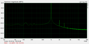
Right Channel
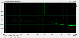
Left Channel

Right Channel

confirm approx. 0V65dc across each R109 and R129
125mV is positive, I resume?
gimme voltage across R118
if that compute (for current thrugh R118) confirming half of current through R109, then back-down with P101, replace R118 with 1K2 , then proceed with setting procedure
Ok update - still got a problem but different problem or original problem still not solved (I think dead bug)
I put fresh IRFP150 in M102 and flying leads (less than 5cm) to offboard M103 but salvaged from earlier attempt.
about 0V58dc (R129) and 0V505 (R109) - 125mV offset was with 0A Iq. With 1.6A Iq, it was around 700mV (positive, yes)
Voltage across R118 was 3.29V and yes, current through R118 was about half of current through R109 so I removed R118 (820R) and tried 1K (not enough) and then 1K5 (820R + 681R) and was able to zero offset stable with Iq stable. Voltage across 1R 3W at 806mV, reading on V+ through clamp meter was 1.65A.
Everything looks good so I clipped the IN+ grounding lead (IN- stayed grounded) and now I have 5.xVdc offset and Iq has dropped to about 100mA (almost zero). Other channel is still fine.

check zeners, for start
try poking with diode test (power off, of course) , comparing things between good and bad channel
I had few channels of these on overhauling, same case as with yours - mistake during assembling (by local guys, who bought the kit) ...... and there were few different scenarios, but non of them having mounted but non soldered output mosfets
if you have any IRFP240 around ( that one most likely, every Papamps having them) try with fresh pair of these
no need for matching
I still haven't gotten my REW mojo 100% in-line, but a kind person did some measurements on my Babel J2 for me. As I learn a bit more about PSUs, I may try to reduce the 60Hz and its harmonics, but I'm very happy. I love the amp without knowing anything about the measurements, but this is nice.
Left Channel
View attachment 869294
Right Channel
View attachment 869295
I’ll try and get some good shots of mine with REW this weekend for comparison. I’m also still dialing in REW, and my setup doesn’t produce anything as clean as these. Nice!
Update
Poked zeners on both channels and they measure the same, also swapped in fresh IRFP150 so both mosfets on channel 2 are new but same behavior. I disconnected channel from test bed and checked on channel 1 and it had 5V+ (positive) offset as well.
What I noticed is that if I turn power off and back on after a minute, the offset and Iq go back to normal and then after a minute or 2 (sporadic, not consistent) it goes crazy and back to 5V offset and 100mA Iq. This is the same for both channels, probably just never ran channel 1 long enough to see this and it only happened after I disconnected input+ from ground. With input+ grounded, both channels are well behaved.
I only got SMD populated boards, not the kit so I sourced my own parts. When I was looking for BC639 and 640 I could only find BC63916 and BC640TA. They both seem to be the right parts NPN and PNP, higher current handling than 550/560 (1A instead of 100mA). I used all BC550CTA and BC560CTA in smaller spots.
BC63916-D27Z ON Semiconductor / Fairchild | Mouser Canada
BC640TA ON Semiconductor / Fairchild | Mouser Canada
Input- is supposed to be grounded for testing as well as normal use if only running SE input correct? Should I start replacing parts or is there enough information to have a suspect yet? Does the drop in Iq from 1.7A down to 100mA provide a clue?
- Home
- Amplifiers
- Pass Labs
- Babelfish ᄅſ....or FW J2 on Steroids .... or Not your Father's J2!
