I started using LTspice not long ago too.
I found this very helpful with step-by-step instructions:
Installing and using LTspice IV (now including LTXVII). From beginner to advanced.
Besides the .tran (Transient) simulation, .ac (AC Analysis) and .four (FFT Analysis) are also interesting.
I also found this for FFT analysis:
Installing and using LTspice IV (now including LTXVII). From beginner to advanced.
The video is very fast paced so I paused it frequently.
If you mean 20Vpp, yes, it should be around 12W/4ohm.
How much is the THD?
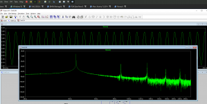
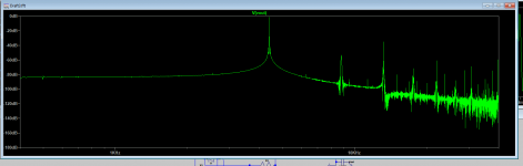
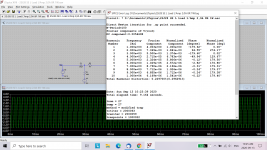
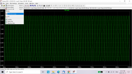
I am not sure I get this right. This is 1 Vpp input 4400Hz, and I put FFT, this i the result...
Attachments
Power output is (Vrms out)squared/Rout, or (0.707 x Vp-p/2)squared/Rout.
The "standard" input frequency that many people use for Distortion analysis is 1000Hz.
For a numerical display of Harmonic distortion, go to "View" and "Spice Error Log".
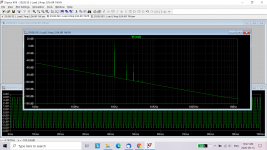
Here is one that I had done of one of my amps:
The "standard" input frequency that many people use for Distortion analysis is 1000Hz.
For a numerical display of Harmonic distortion, go to "View" and "Spice Error Log".
Here is one that I had done of one of my amps:
Attachments
I think verification that your model is representative of the circuit that you are simulating should be done first.
I was looking at your post #42. It is useful to display voltages at key points such as at power supply output and output device drain. Current can also be displayed. See my model in post #50 which displays drain voltage and current.
You have power supply input AC as 100V. That is 100Vp which is 70.7Vrms. I see that NP had a 50VAC (rms) transformer in his schematic http://www.firstwatt.com/pdf/art_delite.pdf Fig, 7). Power supply voltage was given as 65V. Your power supply voltage is probably somewhere between 90 and 100V.
Yes, if you want results for 4 Ohm speaker, place a 4 Ohm resistor at the output. I see that you had done that in your model in post #42.
You should see the "Spice Error Log" option in "View". It is directly above "FFT".
Attachments
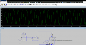
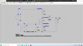
Ben, I worked a little, now seems a better schematic I think.
When in max, I get 16Vp.
I tried many hours of testing, the original schematic included. Same FFT always. I believe that I don't do something correct, since I get 262000 samples on all 3 seconds of the run. Anyway, I ll try it anyways, waiting for parts.
When in max, I get 16Vp.
I tried many hours of testing, the original schematic included. Same FFT always. I believe that I don't do something correct, since I get 262000 samples on all 3 seconds of the run. Anyway, I ll try it anyways, waiting for parts.
Attachments
Yes, it is now much easier to see the operating conditions of your simulation. It does take a bit of time to learn LTspice. I am still learning.
One thing to remember is that it is a simulation. The circuit in real life may not behave exactly as the simulation, as the models for the various components may not behave exactly as the real thing. Modeling and simulation will get you to a starting point but tuning of the real thing will probably be necessary. From that point of view, it is best to not finalize your power supply until you test your build. FFT analysis for harmonic distortion may give results that do not agree with your simulation, and you may not be happy with them, so you may then want to try different operating points.
In your simulation circuit I see that you are running 3.56A through a 0.15H choke. If that is a Hammond 193V, that is higher than its 3.0A rating.
You are also dissipating approximately 270W at the IXTH6N50D2. Data sheets show that it is a 300W device (also see Safe Operating Area graphs). I believe most builders run devices up to 25 or 30 percent of their rating for durability and long life. Of course the cooler you run them (with more heat sinking or active cooling) the more you can probably push them.
https://ixapps.ixys.com/DataSheet/DS100177B(IXTA-TP-TH6N50D2).pdf
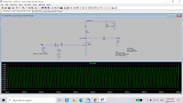
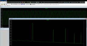
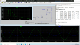
Disregard previous, did my homework, got better, used another example and now makes sense...
Still en error in the log for the FET bu anyways... Here it is...
Run some tests:
1W 0.23% THD
12W 4.2% THD
Still en error in the log for the FET bu anyways... Here it is...
Run some tests:
1W 0.23% THD
12W 4.2% THD
Attachments
Last edited:
You are still running it on the hot side at 97W.
I wonder about the 1W and 12W THD that you posted. The simulation run that you posted showed Vp out of approximately 1.55V at 4R. P= (0.707 x 1.55V)squared/4R= 0.30W. Simulation showed THD = 0.597...%. This is higher than 1W 0.23% THD.
If you are building this circuit, I suggest you do a variation of Fig.10 of http://www.firstwatt.com/pdf/art_delite.pdf (choke load in place of light bulbs). With this circuit, you can adjust Vgs to vary Iq. That gives you flexibility when seeking your preferred operating point. It also has lower distortion so you will get higher usable power.
I would also suggest you start with NP's operating point. He ran it at 2.2A and Vds is somewhere between 30 and 35V. I can't be sure because I am not sure what the light bulb resistance is in that circuit. Simulate with 8R speaker load to start with and compare to NP's measured distortion. Then change simulation to 4R speaker load and see what changes. Then go from there.
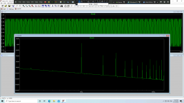
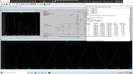
Oh, I changed the values on the circuit, so THD is different.
Now on this example we have 1.7Vp^2 x 0.707 x 4 = 5.6W and THD is 0.46%
Well, as I said this is going to be a proto, I have ordered a 0-90V SPS, so I will play.
For heat, let's see what my liquid cooling will manage.
I will use fig. 7, a I said I don't want the input capacitor. And maybe I will change output capacitor with a coil as plasnu suggested, we will see.
Attachments

- Status
- This old topic is closed. If you want to reopen this topic, contact a moderator using the "Report Post" button.
- Home
- Amplifiers
- Pass Labs
- Inductor Loaded De-Lite