Awesome. Thanks for the photos!
I have to admit.. one of the reasons I wanted to see them, was to see what you had going on that 4 terminal block.. I see the two CL60s.. but is there anything else connected there? I keep seeing a little blue passive something on some builds.. I have been told by JeffYoung that it is a "RFI suppression cap. Note that it must be X2 rated or better." but I need someone to point me to a specific part on digikey or mouser...
Also, I bought the soft start and speaker protection boards... My question is: Should I try to get the basic amp running successfully first, and then add in those two boards? Just to cut down on confusion if something needs troubleshooting? (I'll be testing on beater speakers, so I'm not worried about speaker protection right off the bat.)
Thanks!
It already has a soft start with the CL-60s. As for speaker protection it provides peace of mind, but I never heard of an F5 damaging speakers even when they fail.
Check this out. I think those drivers were 500$ each.
https://www.diyaudio.com/forums/pass-labs/207103-f5-turbo-builders-thread-489.html#post5219322
I ran with no speaker protection on my F5V3s when I had DIY speakers where I knew the bass drivers could be sourced and I knew the cost/ risk involved. When I bought a set of expensive Monitor Audio speakers I re evaluated the risk and installed protection.
Is that the right link? I don't see anything about blowing speaker drivers.
Is that the right link? I don't see anything about blowing speaker drivers.
Look at the picture on the left Of post 4885. Part of the driver was launched across the room. I think he may have posted more pictures later in the thread. That wire you see is the voice coil which was renovated to the outside of the magnetic gap by a bad F5. Reading that build thread is a good preparation for building. There has been a lot of magic smoke let out of a lot of F5 amps. I think it may be the most difficult amp to get right, particularly in the V3 version with multiple boards, lots of output fets and lots of heat. With huge power supplies involved the potential for extensive damage is high.
Last edited:
F5 V3 =/= F5T
I've read all the related threads I could find from end to end re: the F5 (non-turbo) and have not seen an issue of speaker damage. That's not to say it can't happen, or hasn't been posted, just that I have not read it.
Either way, speaker protection is a choice. It could be a smart choice.
I've read all the related threads I could find from end to end re: the F5 (non-turbo) and have not seen an issue of speaker damage. That's not to say it can't happen, or hasn't been posted, just that I have not read it.
Either way, speaker protection is a choice. It could be a smart choice.
I got to sit down and listen to my amp for a little over 3 hours last night.
Quite a range of music genre Rittenour, SRV, Sade, Rikie Lee Jones, Robin Trower and Pink Floyd.
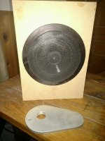
All through some speakers (in ceiling that I got for free when I bought a tv).
I had them laying around and decided to put them in some boxes for my wood shop.
(They didn't make the grade and were replaced by another set from a kit from Meniscus.)
So when I hooked them up I thought it would sound, well, bad.
I have heard far worse, I was amazed that they sounded as good as they did.
Plenty of bass, voices and instruments were clear although a little lacking in the high end but that is the speaker I think.
With what I heard from essentially a single driver speaker, I ordered a pair of Mark Audio 12p drivers.
Now I am all nervous about the speaker protection thing.
I just hope taking Zen Mods advice on keeping the NTC"s not touching the washers keeps me safe
Quite a range of music genre Rittenour, SRV, Sade, Rikie Lee Jones, Robin Trower and Pink Floyd.
All through some speakers (in ceiling that I got for free when I bought a tv).
I had them laying around and decided to put them in some boxes for my wood shop.
(They didn't make the grade and were replaced by another set from a kit from Meniscus.)
So when I hooked them up I thought it would sound, well, bad.
I have heard far worse, I was amazed that they sounded as good as they did.
Plenty of bass, voices and instruments were clear although a little lacking in the high end but that is the speaker I think.
With what I heard from essentially a single driver speaker, I ordered a pair of Mark Audio 12p drivers.
Now I am all nervous about the speaker protection thing.
I just hope taking Zen Mods advice on keeping the NTC"s not touching the washers keeps me safe
Attachments
If your sitting on the fence because you think the wattage is a little low, I will say, this amp puts out plenty, just saying
Maybe? After building the Amp Camp Amp, I was immediately like: "Okay. I should have built a bigger one.." I guess I want to keep my options open for F5 turbo versions?
Which, while I've got your ear... Should I/Could I be building a higher powered (50watt into 8ohm) F5 as Nelson describes in the beginning of the F5 Turbo document? Is there any reason I should do the regular F5 first? It looks like a higher voltage power supply and a couple of other upgraded components would double my wattage?
"Increasing the power supply voltage is the obvious way to get more power out
of an F5. You can simply raise the supply rails to +/-32 Volts and get 50
watts into 8 ohms right away without other modification. 24 V AC secondaries
on the power transformer will do it."
Thanks.. Feel free to tell me to read more forums...
@Flamethrower
You get 0.6 which seems to be the ideal value, congrats, mine won't go over 0.47, I don't know if this is of particular interest to the sonic value of the amp.
A comment on that would be welcome.
On that 6L6 advised me to change R5 & R6 to 4.7k.
I just did today, desoldering isn't an easy task but with the proper tool it went smoothly.
I made a first bias setting at the proper value and let it run the afternoon long.
I'll redo the setting within few days of playing it.
Sound difference ? I didn't really expect much from this beside peace of mind having things done correctly....wait & see.
From what I have read, changing resistor values to get the bias up a little bit and within spec is something that may need to be addressed from build to build.
I think the mention that they include a couple of extra resistors in the f5 parts kit to address this.
As far as which ones and values, follow 6L6's advice, he will steer you in the right direction.
He helped me out immensely.
I think the mention that they include a couple of extra resistors in the f5 parts kit to address this.
As far as which ones and values, follow 6L6's advice, he will steer you in the right direction.
He helped me out immensely.
F5 BUILD
Managed to plug the F5 into my main system.
I know it is not optimal and will eventually be in its own system.
I have obviously spent a lot of time and money going the wrong way.
The sound is very clear, the instruments well defined, just a great sounding amp.
The amp itself is absolutely dead silent between tracks.
I am glad I ventured down this road as it was well out of my "comfort zone".
Thanks to all who have helped
What amazes me is I actually built it
Thanks guys
Attachments
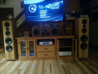
Wait.. Why is it not optimal? I don't understand.. What was the wrong way?!Managed to plug the F5 into my main system.
I know it is not optimal and will eventually be in its own system.
I have obviously spent a lot of time and money going the wrong way.
The sound is very clear, the instruments well defined, just a great sounding amp.
The amp itself is absolutely dead silent between tracks.
I am glad I ventured down this road as it was well out of my "comfort zone".
Thanks to all who have helped
What amazes me is I actually built it
Thanks guys
Nice looking setup!
Not optimal as being in a cabinet, although it does not get as hot as I thought it would.
Could still hold my hand on the heat sinks after a couple of hours of listening to music.
"Wrong way" meaning other than class A amps.
It sits where an XPA2 was and I could very easily live with it.
Could still hold my hand on the heat sinks after a couple of hours of listening to music.
"Wrong way" meaning other than class A amps.
It sits where an XPA2 was and I could very easily live with it.
Onward with Learning
I had my F5 out of my main system for a while, and just put it back in for some fun. As I move along the progression from taking no risks that might involve removing or replacing components... toward "Fearless Amplifier Builder", I am eking along in improving my knowledge base. I'm still in the camp of getting a functioning circuit ... then fiddling a bit. Far from fearless.
I have a few questions. I've read the main "build" threads and as many discussion threads for the First Watt clones I've built thus far (In order of build): M2x, Aleph J, F4, F5, and SissySIT. I've also read a number of others as I try to decide what to build next (ZM's Babelfish F2, then the BA iterations, I think).
All of my builds thus far have been "to the standards" with my only adventures being to move from standard stereo builds to dual mono and to experiment a bit with bias. I haven't fiddled with motor-run caps / inductors in the PSU yet or bypass caps etc. in the signal path. Right now, I'm trying to learn what the "big knobs" do.
So - onto it. I have been curious about the bias discussions, and it seems reasonably easy to have some fun with.
Background - I've fiddled with bias on three amps. With the Aleph J and F4, it seems that I actually preferred my "initial" bias settings or only slightly higher. With the F5, I went from 600mV (~1.3A) across the resistors up to 750mV (1.6A). I seem to prefer the highest bias. I plan on repeating some of the fun. If it matters much, I am using two DIYA UPSs with 8 x 18,000 uF caps and two Antek 400VA donuts in a 5U Deluxe chassis. Also, my speakers (Tekton DIs) may not be as "easy to drive" as I had thought.
A lot of these questions have been asked and answered, but I want to make sure I understand before proceeding. I'm also trying to learn how to interpret spec sheets, which will take me a while. I put this in the F5 thread, because it's the amp I'm currently fiddling with, but I refer to other amps.
1) Temperature on the sinks and devices. This seems to be related more to personal comfort and safety per posts, but the common theme seems to be don't go over 55C on sinks. I am completely fine with going higher, but I've never even reached 55 on the sinks with any of the amps even on the highest biases. I'm also wondering if any of the other devices (like the input stage JFETs in some cases) would be affected?
Overall, it may seem odd, but what I'd like to do if no major operating barriers are broken, and if I've got enough heat sinking is to set the "actual" bias for all the amplifiers as close to the same as practical and hear the difference. Maybe bump them all up to 1A8 if I've got enough heatsinking and rock on.
Any concerns or things that I've gone bonkers with? I'm still reading the threads re: dissipation for heatsinks.... with the amps using more than two devices per channel, I may run out of heatsinking before I can get up to 1A8, but why not try... right... ????
With kind thanks for any pointers.
I had my F5 out of my main system for a while, and just put it back in for some fun. As I move along the progression from taking no risks that might involve removing or replacing components... toward "Fearless Amplifier Builder", I am eking along in improving my knowledge base. I'm still in the camp of getting a functioning circuit ... then fiddling a bit. Far from fearless.
I have a few
questions. I've read the main "build" threads and as many discussion threads for the First Watt clones I've built thus far (In order of build): M2x, Aleph J, F4, F5, and SissySIT. I've also read a number of others as I try to decide what to build next (ZM's Babelfish F2, then the BA iterations, I think).All of my builds thus far have been "to the standards" with my only adventures being to move from standard stereo builds to dual mono and to experiment a bit with bias. I haven't fiddled with motor-run caps / inductors in the PSU yet or bypass caps etc. in the signal path. Right now, I'm trying to learn what the "big knobs" do.
So - onto it. I have been curious about the bias discussions, and it seems reasonably easy to have some fun with.
Background - I've fiddled with bias on three amps. With the Aleph J and F4, it seems that I actually preferred my "initial" bias settings or only slightly higher. With the F5, I went from 600mV (~1.3A) across the resistors up to 750mV (1.6A). I seem to prefer the highest bias. I plan on repeating some of the fun. If it matters much, I am using two DIYA UPSs with 8 x 18,000 uF caps and two Antek 400VA donuts in a 5U Deluxe chassis. Also, my speakers (Tekton DIs) may not be as "easy to drive" as I had thought.
A lot of these questions have been asked and answered, but I want to make sure I understand before proceeding. I'm also trying to learn how to interpret spec sheets, which will take me a while. I put this in the F5 thread, because it's the amp I'm currently fiddling with, but I refer to other amps.
1) Temperature on the sinks and devices. This seems to be related more to personal comfort and safety per posts, but the common theme seems to be don't go over 55C on sinks. I am completely fine with going higher, but I've never even reached 55 on the sinks with any of the amps even on the highest biases. I'm also wondering if any of the other devices (like the input stage JFETs in some cases) would be affected?
a) There are a few temperature specifications within the IRFP240 and 9240 data sheets. Admittedly, I haven't learned enough to make sense of the specs, or the thermal graphs. The question is, If I separate the personal safety aspect of hot heatsinks - Is there a recommended / safe limit for longer life for the temp of the devices themselves? If so, which spec would I refer to? I don't want to shorten the life of the amps appreciably, nor just "burn one up" by accident.
b) The performance of the device does seem to vary with absolute temperature. However, once the amplifier as a whole reaches relative equilibrium, will one operating temp be better or worse for these devices within the norms of what we're using them for here?
c) Does bias affect any of the other components? I don't think so, but wanted to confirm.
2) Operating bias current / measurement voltage / Maximum dissipated power.b) The performance of the device does seem to vary with absolute temperature. However, once the amplifier as a whole reaches relative equilibrium, will one operating temp be better or worse for these devices within the norms of what we're using them for here?
c) Does bias affect any of the other components? I don't think so, but wanted to confirm.
a) I've read that we don't want to exceed 30W per device. Where does that come from on the specs? Also, if we're calculating this - does it come from simply the rail voltages * the bias current? If so, how does one properly measure rail voltages under load? Is it as simple as measuring V+ and V- with the amp boards connected and biased?
b) Is there an "ideal" bias current for each device or pair of devices (separate from matching)? That may be a bit out of my depth for the moment, but I thought I'd ask re: some general trends. With the exception of the M2x, all my devices came from the same sleeves. They all were within the recommended matching Vgs at 22V 0A4. I measured and sorted them all, because why not. So, they should be very tightly matched within Ns or Ps even across amps. I got lucky that even the Ns and Ps are close. I don't think there's anything out there that requires Ns and Ps to match, but it sure seems to make nulling DC offset a breeze. Of course I could be imagining things too.
c) If I am calculating correctly from the measured voltages and estimated rails under load, at the moment, my boards are set up as follows with the Panasonic 0R47 resistors at all spots:
i. F5 - Across R7, and R8 - 750mV. OR47. 22V => 1A6 bias. 35.2W - This one seems to jive with what I'm beginning to understand.
ii.F4 - Across Source Resistors - 200mV. OR47. 22V => 0A42 bias. 9.36W. This does not seem to jive. Is it because the devices are in parallel? How would one properly calculate the bias / watts?
iii. AJ - Across R18 - 400mV. 0R47. 22V => 0A85 bias. 18.72W.
I think understand that we're not really altering the "bias", but the operating point for the CCS. That's a bit over my head, but how would I calculate the bias or rough it in? Again, I think I may be calculating incorrectly...
iv. M2x - Autobiasing. Per build threads, it's "about 1A5". No measurement.
33W. I'm not sure I want to go swapping out parts to change bias, but if I were to consider it... I'll ask over in the proper thread.
v. SissySIT - Across PSU resistors - 4x0R47: 200mA. 1A8. ~40W Makes sense. Note, one device is the Tokin SIT in a different package, but one is also a standard IRFP.
d) Last but not least - I've read that reducing the source resistance for some of the amps can be beneficial, thus allowing more current with no detrimental effects (if output devices are matched tightly enough). I'm not ready to take that on quite yet, but if I can simply increase the bias - why would this help? I understand why they're used to help ensure one device is not a "current hog", but if my limitation is heatsinking and/or device temperature - why will this help?
Overall, it may seem odd, but what I'd like to do if no major operating barriers are broken, and if I've got enough heat sinking is to set the "actual" bias for all the amplifiers as close to the same as practical and hear the difference. Maybe bump them all up to 1A8 if I've got enough heatsinking and rock on.
Any concerns or things that I've gone bonkers with? I'm still reading the threads re: dissipation for heatsinks.... with the amps using more than two devices per channel, I may run out of heatsinking before I can get up to 1A8, but why not try... right... ????
With kind thanks for any pointers.
Ok, I'm close to starting the F6 stereo build and have all the parts (I think) that I need with exception to the Power Supply Board and the components that go on it.
I see I can order the board on the DIY store site but it looks like the actual caps and other parts are not sold as a kit on the site. The only parts list I can find are on the Build Guide but look to be from 2015 or so and I see mention of tweaks/changes etc.
Is there a current parts list for the board and if so any advice on which supplier to buy them from ?
thanks
I had my F5 out of my main system for a while, and just put it back in for some fun. As I move along the progression from taking no risks that might involve removing or replacing components... toward "Fearless Amplifier Builder", I am eking along in improving my knowledge base. I'm still in the camp of getting a functioning circuit ... then fiddling a bit. Far from fearless.
I have a few
All of my builds thus far have been "to the standards" with my only adventures being to move from standard stereo builds to dual mono and to experiment a bit with bias. I haven't fiddled with motor-run caps / inductors in the PSU yet or bypass caps etc. in the signal path. Right now, I'm trying to learn what the "big knobs" do.
So - onto it. I have been curious about the bias discussions, and it seems reasonably easy to have some fun with.
Background - I've fiddled with bias on three amps. With the Aleph J and F4, it seems that I actually preferred my "initial" bias settings or only slightly higher. With the F5, I went from 600mV (~1.3A) across the resistors up to 750mV (1.6A). I seem to prefer the highest bias. I plan on repeating some of the fun. If it matters much, I am using two DIYA UPSs with 8 x 18,000 uF caps and two Antek 400VA donuts in a 5U Deluxe chassis. Also, my speakers (Tekton DIs) may not be as "easy to drive" as I had thought.
A lot of these questions have been asked and answered, but I want to make sure I understand before proceeding. I'm also trying to learn how to interpret spec sheets, which will take me a while. I put this in the F5 thread, because it's the amp I'm currently fiddling with, but I refer to other amps.
1) Temperature on the sinks and devices. This seems to be related more to personal comfort and safety per posts, but the common theme seems to be don't go over 55C on sinks. I am completely fine with going higher, but I've never even reached 55 on the sinks with any of the amps even on the highest biases. I'm also wondering if any of the other devices (like the input stage JFETs in some cases) would be affected?
a) There are a few temperature specifications within the IRFP240 and 9240 data sheets. Admittedly, I haven't learned enough to make sense of the specs, or the thermal graphs. The question is, If I separate the personal safety aspect of hot heatsinks - Is there a recommended / safe limit for longer life for the temp of the devices themselves? If so, which spec would I refer to? I don't want to shorten the life of the amps appreciably, nor just "burn one up" by accident.2) Operating bias current / measurement voltage / Maximum dissipated power.
b) The performance of the device does seem to vary with absolute temperature. However, once the amplifier as a whole reaches relative equilibrium, will one operating temp be better or worse for these devices within the norms of what we're using them for here?
c) Does bias affect any of the other components? I don't think so, but wanted to confirm.
a) I've read that we don't want to exceed 30W per device. Where does that come from on the specs? Also, if we're calculating this - does it come from simply the rail voltages * the bias current? If so, how does one properly measure rail voltages under load? Is it as simple as measuring V+ and V- with the amp boards connected and biased?
b) Is there an "ideal" bias current for each device or pair of devices (separate from matching)? That may be a bit out of my depth for the moment, but I thought I'd ask re: some general trends. With the exception of the M2x, all my devices came from the same sleeves. They all were within the recommended matching Vgs at 22V 0A4. I measured and sorted them all, because why not. So, they should be very tightly matched within Ns or Ps even across amps. I got lucky that even the Ns and Ps are close. I don't think there's anything out there that requires Ns and Ps to match, but it sure seems to make nulling DC offset a breeze. Of course I could be imagining things too.
c) If I am calculating correctly from the measured voltages and estimated rails under load, at the moment, my boards are set up as follows with the Panasonic 0R47 resistors at all spots:i. F5 - Across R7, and R8 - 750mV. OR47. 22V => 1A6 bias. 35.2W - This one seems to jive with what I'm beginning to understand.
ii.F4 - Across Source Resistors - 200mV. OR47. 22V => 0A42 bias. 9.36W. This does not seem to jive. Is it because the devices are in parallel? How would one properly calculate the bias / watts?
iii. AJ - Across R18 - 400mV. 0R47. 22V => 0A85 bias. 18.72W.
I think understand that we're not really altering the "bias", but the operating point for the CCS. That's a bit over my head, but how would I calculate the bias or rough it in? Again, I think I may be calculating incorrectly...
iv. M2x - Autobiasing. Per build threads, it's "about 1A5". No measurement.
33W. I'm not sure I want to go swapping out parts to change bias, but if I were to consider it... I'll ask over in the proper thread.
v. SissySIT - Across PSU resistors - 4x0R47: 200mA. 1A8. ~40W Makes sense. Note, one device is the Tokin SIT in a different package, but one is also a standard IRFP.
d) Last but not least - I've read that reducing the source resistance for some of the amps can be beneficial, thus allowing more current with no detrimental effects (if output devices are matched tightly enough). I'm not ready to take that on quite yet, but if I can simply increase the bias - why would this help? I understand why they're used to help ensure one device is not a "current hog", but if my limitation is heatsinking and/or device temperature - why will this help?
Overall, it may seem odd, but what I'd like to do if no major operating barriers are broken, and if I've got enough heat sinking is to set the "actual" bias for all the amplifiers as close to the same as practical and hear the difference. Maybe bump them all up to 1A8 if I've got enough heatsinking and rock on.
Any concerns or things that I've gone bonkers with? I'm still reading the threads re: dissipation for heatsinks.... with the amps using more than two devices per channel, I may run out of heatsinking before I can get up to 1A8, but why not try... right... ????
With kind thanks for any pointers.
From Nelson in an earlier post:
Technically, the junctions of the devices are rated at 150 deg C. If you are running as high as 50 watts per device, then you will want to measure well less than 100 deg C on the case (you can use a cheap Radio Shack IR thermometer). Don't expect them to have a long life span at those figures, but I have seen reasonable reliability at 25 deg less junction temp.
My F5 has been in my main system for a while now and I have really grown to like and appreciate this amp.
The clarity, over what I had before is amazing.
I can say I have never had a system that sounds like this.
Sorry about the fork thing.
It was never meant to imply that this stuff is easy, just my humor over a personal first.
Anyway, again, thanks to all who helped.
Hope you all have a wonderful Christmas
- Status
- This old topic is closed. If you want to reopen this topic, contact a moderator using the "Report Post" button.
- Home
- Amplifiers
- Pass Labs
- F5 V3