Hi DIYers,
I'll be posting my progress throughout my M2x build.
I started this thread for a few reasons.
1) To say thank you to all the DIYers and a few people specifically: Nelson, Wayne, Jim, and Mark. There’s no way in the world I could have built the WHAMMY or feel prepared to build the M2x without your collective generosity.
2) I hope it helps someone. All of the answers are out there. Either they're already documented or in the heads of the fine folks that frequent the forum. With that said, I’ve read countless pages and cut and pasted materials into my horribly disorganized build notes and learning guides. I’ve been trying to drink from the firehose, and I am still a bit intimidated. But, if it weren’t a challenge, it won’t be as sweet when I finish. I’ve learned that this community ranges from people like me that are barely beyond "Legos for adults" to people that understand every last aspect of the circuits and design their own. Maybe this can help a fellow Lego junky.
3) Selfishness… Announcing to the world I’m trying to do this will keep me accountable to finish it. Also, I will certainly need more advice.")
To understand the choices I’ve already made, it may help to know a few things. My long-term goal is to build as many First Watt clones and other DIYAudio amps as practical while learning a bit more about electronics and audio circuits along the way. I am a complete newcomer to DIY and electronics. I picked up a soldering iron for the first time in over 25ish years just a few months ago and have never had any formal training in electronics. I watched a bunch of YouTube to learn how to solder a bit. I practiced, burnt up a lot of parts and a practice board or two, found decent magnification that works for my lousy vision, improved my technique and tools, and I caught the bug. I built 3 headphone amps. I love the builds, and I've found some great sounding amps.
My primary considerations for this build were my experience, my current loudspeaker system, and cost. Secondary considerations were longer-term cost of building additional amps and flexibility. I want to get a working amp first. I can “get greedy” later. Much later.
So on to it. Over the last four weeks:
• I chose the M2x as my first First Watt build.
• I read the M2x, M2 “Tea-Bag”, and UPS build guides/threads from end to end. I read/skimmed other threads while choosing the amp I wanted to build. The Aleph and the BA3 were in the finals. The BA3 build seemed a bit more than I wanted to take on right now, and the Aleph may be my next build. I have fairly efficient speakers, so the First Watt amps will serve me well. I plan to try a few “higher horsepower variants” later, but I wanted to reduce complexity.
• I chose to use the 5U Deluxe with all the holes tapped and the rear panel kit. The WHAMMY (Hammond) case took me quite some time. It looks good, but I have a fear of botching an expensive case. I can further customize or learn to do some metal work in the future. I want to maximize chances of success while reducing complexity. I also have plenty of space to put the big honking chassis. I think having more space will make it a bit easier to minimize chances of any noise and make it easier on a noob.
• I chose to use the 400VA Antek AS4218 transformer that many folks seem familiar with. I was originally going for the “biggest must be best and more future proof”, but wise guidance prevailed. 400VA is more than enough for the First Watt builds. I had considered the PSU in a separate enclosure, but that's too much for a first timer. I can always move it later. I'd like to have the Antek case, but they're out of stock for the time being.
• I sourced all of the BOMs for the M2x and daughterboards along with the DIYAudio Unversal Power Supply. This took me far longer than I anticipated, but I learned quite a bit. I chose to use the separate diodes vs. a monolithic rectifier on the power supply. Power supply cap choice seems to be a well-discussed topic. To other newcomers, read as much as you can. I have learned (or been told rather) that the biggest is not always the best. I grasp a bit of the "why". I chose 18,000uf. I am not sure if I’ll use the heatsinks on the diodes or not. I think a well-trusted source said they’re not needed, but I need to review my notes. I have them anyway, so unless I can save them for another project, I may as well use them.
I literally spent days agonizing over the BOMs. I am sure that’s not necessary, but I learned a lot and asked a lot of questions. I got some great advice that’s over in the build guide thread re: choosing resistor ratings. After hours of reading, I also learned (I think) what input snubbers do in a power supply, and a kind person gave me suggested values for the caps and resistors based on my transformer choice.
Figuring out what parts you need is one thing, finding them and learning the interfaces for various suppliers is another to find equivalent parts. Learning what specs "matter" when choosing alternatives is not my best idea of fun yet. Inventory changes far more quickly than I anticipated, and I finally figured out how not to choose a part where the MOQ was 1000
I'll say this, when Mouser FINALLY showed all the parts I had chosen were in stock, it was a bit of a thrill.
• I ordered up all the parts with the exception of some quick connectors. I’m sure a few other things I missed that will cause me to cuss and delay the process a bit…
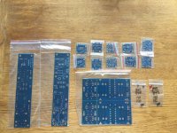
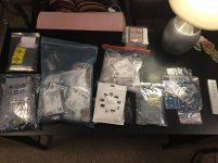
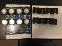
Here’s a pic of the gorgeous new boards and the JFETs for the Ishikawa board. I should have the iron hot before the end of the week.
Here we go!
I'll be posting my progress throughout my M2x build.
I started this thread for a few reasons.
1) To say thank you to all the DIYers and a few people specifically: Nelson, Wayne, Jim, and Mark. There’s no way in the world I could have built the WHAMMY or feel prepared to build the M2x without your collective generosity.
2) I hope it helps someone. All of the answers are out there. Either they're already documented or in the heads of the fine folks that frequent the forum. With that said, I’ve read countless pages and cut and pasted materials into my horribly disorganized build notes and learning guides. I’ve been trying to drink from the firehose, and I am still a bit intimidated. But, if it weren’t a challenge, it won’t be as sweet when I finish. I’ve learned that this community ranges from people like me that are barely beyond "Legos for adults" to people that understand every last aspect of the circuits and design their own. Maybe this can help a fellow Lego junky.
3) Selfishness… Announcing to the world I’m trying to do this will keep me accountable to finish it. Also, I will certainly need more advice.
To understand the choices I’ve already made, it may help to know a few things. My long-term goal is to build as many First Watt clones and other DIYAudio amps as practical while learning a bit more about electronics and audio circuits along the way. I am a complete newcomer to DIY and electronics. I picked up a soldering iron for the first time in over 25ish years just a few months ago and have never had any formal training in electronics. I watched a bunch of YouTube to learn how to solder a bit. I practiced, burnt up a lot of parts and a practice board or two, found decent magnification that works for my lousy vision, improved my technique and tools, and I caught the bug. I built 3 headphone amps. I love the builds, and I've found some great sounding amps.
My primary considerations for this build were my experience, my current loudspeaker system, and cost. Secondary considerations were longer-term cost of building additional amps and flexibility. I want to get a working amp first. I can “get greedy” later. Much later.
So on to it. Over the last four weeks:
• I chose the M2x as my first First Watt build.
• I read the M2x, M2 “Tea-Bag”, and UPS build guides/threads from end to end. I read/skimmed other threads while choosing the amp I wanted to build. The Aleph and the BA3 were in the finals. The BA3 build seemed a bit more than I wanted to take on right now, and the Aleph may be my next build. I have fairly efficient speakers, so the First Watt amps will serve me well. I plan to try a few “higher horsepower variants” later, but I wanted to reduce complexity.
• I chose to use the 5U Deluxe with all the holes tapped and the rear panel kit. The WHAMMY (Hammond) case took me quite some time. It looks good, but I have a fear of botching an expensive case. I can further customize or learn to do some metal work in the future. I want to maximize chances of success while reducing complexity. I also have plenty of space to put the big honking chassis. I think having more space will make it a bit easier to minimize chances of any noise and make it easier on a noob.
• I chose to use the 400VA Antek AS4218 transformer that many folks seem familiar with. I was originally going for the “biggest must be best and more future proof”, but wise guidance prevailed. 400VA is more than enough for the First Watt builds. I had considered the PSU in a separate enclosure, but that's too much for a first timer. I can always move it later. I'd like to have the Antek case, but they're out of stock for the time being.
• I sourced all of the BOMs for the M2x and daughterboards along with the DIYAudio Unversal Power Supply. This took me far longer than I anticipated, but I learned quite a bit. I chose to use the separate diodes vs. a monolithic rectifier on the power supply. Power supply cap choice seems to be a well-discussed topic. To other newcomers, read as much as you can. I have learned (or been told rather) that the biggest is not always the best. I grasp a bit of the "why". I chose 18,000uf. I am not sure if I’ll use the heatsinks on the diodes or not. I think a well-trusted source said they’re not needed, but I need to review my notes. I have them anyway, so unless I can save them for another project, I may as well use them.
I literally spent days agonizing over the BOMs. I am sure that’s not necessary, but I learned a lot and asked a lot of questions. I got some great advice that’s over in the build guide thread re: choosing resistor ratings. After hours of reading, I also learned (I think) what input snubbers do in a power supply, and a kind person gave me suggested values for the caps and resistors based on my transformer choice.
Figuring out what parts you need is one thing, finding them and learning the interfaces for various suppliers is another to find equivalent parts. Learning what specs "matter" when choosing alternatives is not my best idea of fun yet.
Inventory changes far more quickly than I anticipated, and I finally figured out how not to choose a part where the MOQ was 1000 I'll say this, when Mouser FINALLY showed all the parts I had chosen were in stock, it was a bit of a thrill.
• I ordered up all the parts with the exception of some quick connectors. I’m sure a few other things I missed that will cause me to cuss and delay the process a bit…
Here’s a pic of the gorgeous new boards and the JFETs for the Ishikawa board. I should have the iron hot before the end of the week.
Here we go!
Attachments
Last edited:
To solder the amp boards are the easy part. Mounting diodes on heatsinks and get everything to fit nicely and have the diodes electrical isolated from the heatsink takes a little time. But it is everything around it which really takes time before you have a working amp ….so enjoy soldering and spend some time to ensure you do not make any errors (wrong components, wrong mounted components, cold solder joints etc.).
….so enjoy soldering and spend some time to ensure you do not make any errors (wrong components, wrong mounted components, cold solder joints etc.).Hello ItsAllInMyHead,
I think you are well prepared. Reading the build guides and the M2X-thread
will help you a lot. And here are many members who will try to help you -
if there will be problems.
If I am allowed to give you a few tips (from my experiences with the M2X):
The main boards/ pcbs are not exactly symmetrical (left / right channel).
So be careful when implementing the parts. I work always on one part and
solder it to left and right channel.
I measure each and every resistor with the DMM before soldering in!
The EDCOR transformers have pins which fit only in one direction on the pcb.
Normally the pins should move smoothly into the pcb.
And I would make the 'blasphemous heresy' change to resistor
R6 and RV1 on the mainboard.
R6 changed to anything around 37kOhm to 39 kOhm
RV1 changed to a 20 kOhm trimpot (adjusted to mid position = 10 kOhm).
It doesn't harm but gives you the possibility for wider adjustments (offset at
speakeroutput).
If your M2X is finished and then you have to desolder the trimpot and the resistor (or solder a second one over the original) is no fun - especially for a newbie.
If you brake the PSU boards in the mid - don't mix up the correct side / orientation.
Only some thoughts.
Have fun! Take your time. A M2X is not build in an afternoon!
But the result will be well worth the efforts.
Greets
Dirk
To solder the amp boards are the easy part. Mounting diodes on heatsinks and get everything to fit nicely and have the diodes electrical isolated from the heatsink takes a little time. But it is everything around it which really takes time before you have a working amp
Thank you, @MEPER! Specific to the DIYAudio UPS - I am still not sure I'll be using heatsinks on the diodes I've chosen for the PSU. Leaving them off removes a bit of complexity from the build, and I can maybe save them for another project. I also have in my notes that the diodes do not need to be electrically isolated from the heatsinks. If I do use the heatsinks, I'll still isolate them because it is inexpensive, and I am never 100% sure. So I will err on the side of caution. I have a mounting "kit" from the same manufacturer as the heatsinks. Fortunately, I've done similar work in two other builds, so I am hoping it will go smoothly if I do decide to use them. <crossing fingers>
Note to anyone considering whether they need heatsinks and isolation from them if used- Read and ask questions over in the build guide thread(s). The parts I am using may allow me to not use the heatsinks in this build. Yours may require them. Anything related to "why" should be directed to the experts. I am still learning and undecided. When in doubt, my humblest of advice is to ask in the appropriate thread(s). This thread is not a build guide. The last thing I want to do is cause confusion and remove attention from the official thread(s). When I have questions, that's where I'll be posting them. The collective wisdom of the group is there.
Hello ItsAllInMyHead,
I think you are well prepared. Reading the build guides and the M2X-thread
will help you a lot. And here are many members who will try to help you -
if there will be problems.
If I am allowed to give you a few tips (from my experiences with the M2X):
The main boards/ pcbs are not exactly symmetrical (left / right channel).
So be careful when implementing the parts. I work always on one part and
solder it to left and right channel.
I measure each and every resistor with the DMM before soldering in!
The EDCOR transformers have pins which fit only in one direction on the pcb.
Normally the pins should move smoothly into the pcb.
And I would make the 'blasphemous heresy' change to resistor
R6 and RV1 on the mainboard.
R6 changed to anything around 37kOhm to 39 kOhm
RV1 changed to a 20 kOhm trimpot (adjusted to mid position = 10 kOhm).
It doesn't harm but gives you the possibility for wider adjustments (offset at
speakeroutput).
If your M2X is finished and then you have to desolder the trimpot and the resistor (or solder a second one over the original) is no fun - especially for a newbie.
If you brake the PSU boards in the mid - don't mix up the correct side / orientation.
Only some thoughts.
Have fun! Take your time. A M2X is not build in an afternoon!
But the result will be well worth the efforts.
Greets
Dirk
Thank you, Dirk!
It makes me feel great to know that I had planned to implement all of your suggestions already. Your tips are still greatly appreciated, please continue! It reinforces what I was planning and gives me more confidence.
Further expanding - my general method is:
- I always follow my build sequence / plan for each board set separately even though some boards share common parts. Reversing that, I never pull out all of one part and then install them everywhere they go on all boards. I'll be building the Ishikawa boards first, then the UPS boards, then the amp boards. That sequence feels good. I may or may not wait to have a fully functioning amp prior to building the rest of the daughter boards. Usually when I solder, I get into a groove and the quality is better if I work continuously for a few hours. I'll most likely build the rest of the daughter boards in the following order: Tuscon, Mountain View, Austin, Norwood.
- I keep an updated schematic with my notes printed near my table. I use big-red markings for any changes from the schematic and things like "NO" written over C0. C0 is not on my personal BOM or in my build, but I try to be thorough.
- I have a process in place for assembling each board. I find the parts on my printed build sheet (I marked my BOM with a build order and sorted it), pull ONLY those parts, measure and confirm only those parts, confirm their placement and ensure the part matches the board location and schematic again. Then I install the parts and inspect the joints. If the joints look good, I cross the part off of the build sequence list. It takes longer than stuffing multiple parts at a time, but it helps me prevent mistakes. I try to only have one part that I am installing on the board on my work table. I keep everything else out of reach on another staging table. Too many parts look alike to me with my poor eyesight. Grabbing the wrong one can cause too much trouble. I'm in no hurry. This is the fun part for me! I put this process in place after mixing an N and P channel MOSFET on my WHAMMY build. I found it during my inspection prior to going further in the build, but I really don't like desoldering (particularly heatsinks and multi-pin parts)
- I've ordered the heretical parts
There seems to be absolutely no disadvantage. My R6 is 36.5 ohm, which I've confirmed will be appropriate. I wondered whether using the smaller original values would allow "finer tuning" within the resistance range. A kind person dispelled that myth. I'd rather not take the chance and need to add resistance later. They go in.- I'm not breaking the PSU board.
There seem to be some very good reasons to leave it intact even if I don't fully understand all those reasons yet. That is one of the reasons I went with the 5U deluxe chassis. I am reasonably sure that I can fit the full PSU board using the separate diodes into the build together with the 400VA transformer and still leave appropriate room between the power transformer and the Edcors. I won't have the Antek case for the power transformer for the initial start-up, and I won't be using the tape or mu metal around my Edcors (yet). Physical separation is my friend.
My sincere thanks again to you both!
-Patrick
Before mounting the Edcor - I would suggest wrapping a band of mu metal around it and then putting a mu metal box over the top of it after it is soldered. The thin foil stuff that cuts with scissors works great and brings EMI pickup noise from 600uV rms down to 200uV rms. An essential upgrade. For me, I could not live without the mu metal shield. Look for links to it in M2X thread.
Here is an example of my mu metal box over the Edcor.
Another upgrade you might consider is the SLB PSU. It uses an active bridge with an IC and MOSFETs which are quieter, makes no heat like a diode (since no 0.6v drop) and gives a bit more headroom. However it requires an Antek AS-3222 to provide some voltage drop across the cap multiplier. But you will have 25v rails (vs 22v rails with an Antek 18v) for a bit more headroom in power. Plus, the voltage ripple presented at the amp is only 1mV rms. Makes the amp super quiet. But it looks like you already got the standard CRC PSU so you will use that I guess. Just know that there are state-of-the-art higher performing alternatives to a bog-standard diode bridge/CRC design that’s been in use for the past 60 years. Cost wise about the same since you are using half the number of bulk caps. Also, pay careful attention to the overall grounding scheme to avoid ground loop hum (on top of EMI hum in the Edcor).
Last edited:
WOW! Thanks @XRK971 -
I took all your advice to heart, and I may implement some of the suggestions later or come back to you for advice. I can't stress enough how new I am to all of this. So, simplicity and keeping things in the build that I know I can execute is my priority for now. Also, I'm a bit over budget
I weighed heavily whether to do anything with the mu metal or other direct shielding like the 3M tape on the Edcors. It seems others have been very successful with no shielding as yet. I am using a decent / shielded power transformer that will eventually be housed in a "Faraday Cage" (I still think that's cool). I also have a big chassis. So, I don't want to risk damaging the delicate Edcors. My physical coordination and eyesight are not top notch. If I do have some noise, I can always add the shielding around the Edcors at a later date. I've read two or more situations where folks more skilled than I had some difficulty. So, I'm holding off. I bought some spares to use later. To give you an idea of my lack of skills... I'd have no idea how to properly mount the box if I assembled it. I've seen questions about isolating it from the transformer itself and grounding it. It's all a bit too much for me at this point in the bigger picture of the build. A person like you can maybe put one together quickly and instinctively know how it should all go together. For me, we're talking days for me to even plan it out. I'd worry about it shorting against pads nearby etc. The choice has been made to leave it out (for now).
re: the power supply. I've already sourced everything and have the parts on the way, so I won't be making any changes at this particular point in the process. You've given me some fantastic ideas for potential future upgrades. By that point, I may even have some of my own measuring gear to help me understand the changes and allow me to do an A/B. I love that the experts like you have moved beyond the standards and pave the way for us noobs, but for now... I have to keep it easy.
re: Grounding schemes - It seems there are a number of options with quick-connects all over the boards for shuffling things around as needed. Again, the great news is that if I have noise due to a loop after the first and most simple build, I can troubleshoot and hopefully make some very simple changes. It took me a few hours to understand what a "star ground" was. Many terms that are posted on the forums fly right over my head. I'm still a kit assembler. I don't have any real knowledge (yet).
Truly appreciate the input!
I took all your advice to heart, and I may implement some of the suggestions later or come back to you for advice. I can't stress enough how new I am to all of this. So, simplicity and keeping things in the build that I know I can execute is my priority for now. Also, I'm a bit over budget
I weighed heavily whether to do anything with the mu metal or other direct shielding like the 3M tape on the Edcors. It seems others have been very successful with no shielding as yet. I am using a decent / shielded power transformer that will eventually be housed in a "Faraday Cage" (I still think that's cool). I also have a big chassis. So, I don't want to risk damaging the delicate Edcors. My physical coordination and eyesight are not top notch. If I do have some noise, I can always add the shielding around the Edcors at a later date. I've read two or more situations where folks more skilled than I had some difficulty. So, I'm holding off. I bought some spares to use later. To give you an idea of my lack of skills... I'd have no idea how to properly mount the box if I assembled it. I've seen questions about isolating it from the transformer itself and grounding it. It's all a bit too much for me at this point in the bigger picture of the build. A person like you can maybe put one together quickly and instinctively know how it should all go together. For me, we're talking days for me to even plan it out. I'd worry about it shorting against pads nearby etc. The choice has been made to leave it out (for now).
re: the power supply. I've already sourced everything and have the parts on the way, so I won't be making any changes at this particular point in the process. You've given me some fantastic ideas for potential future upgrades. By that point, I may even have some of my own measuring gear to help me understand the changes and allow me to do an A/B.
I love that the experts like you have moved beyond the standards and pave the way for us noobs, but for now... I have to keep it easy.re: Grounding schemes - It seems there are a number of options with quick-connects all over the boards for shuffling things around as needed. Again, the great news is that if I have noise due to a loop after the first and most simple build, I can troubleshoot and hopefully make some very simple changes. It took me a few hours to understand what a "star ground" was. Many terms that are posted on the forums fly right over my head. I'm still a kit assembler. I don't have any real knowledge (yet).
Truly appreciate the input!
With some thoughtful positioning of the main channel boards and power supply components, plus careful dressing of the wiring, your M2x can be essentially hum-free without resorting to heroic measures. The big 5U Deluxe chassis gives you plenty of room for some different options, including mounting the transformer vertically, either to the inside of the thick face plate or using right angle brackets of some sort. That seems to have worked for several builders who didn't have a steel case for their toroid. The galvanized steel inner base plate is great for mounting the heavy toroid if you don't want to go to the extra trouble of mounting it vertically. The inner baseplate will also let you run the AC wiring between it and the outer base plate, to have another quasi Faraday cage to shield your Edcors from line frequency interference.
I recommend connecting the negative speaker binding posts directly to the ground attachment points on the Universal PSU. Each of the main channel boards still needs its own ground wire, which can be routed in parallel with the positive speaker output. The VPOS and VNEG supply wires should be routed in parallel between each channel board and the PSU. See post #1666 in the M2x thread for a picture of how this was done.
I recommend connecting the negative speaker binding posts directly to the ground attachment points on the Universal PSU. Each of the main channel boards still needs its own ground wire, which can be routed in parallel with the positive speaker output. The VPOS and VNEG supply wires should be routed in parallel between each channel board and the PSU. See post #1666 in the M2x thread for a picture of how this was done.
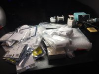
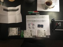
Today was a GREAT day. I got a haul from Mouser, the DIYAudio store and Amazon.
The vast majority of the parts for the amp boards, the PSU, and the daughter boards arrived. I also got my back panel kit and Keratherm pads and some tools, nuts and bolts etc, from Amazon.
I've since learned I need a few other things I missed, like inrush limiters (CL-60s). So, I am trying to get one final list of things I need.
A couple things I've learned so far that may help other newcomers.
1) If you plan to order a whole project worth of parts and accessories all at once, learn to use the BOM tools in Mouser, Digi-Key or your favorite source. It makes life so much easier. I moved the downloaded BOM spreadsheets for this build (and copied from .pdfs for another build). I then cross referenced all parts and found substitutes as needed along with finding parts with no part numbers.
I created my own BOM files. When I needed a substitute part or made a choice between options, I made absolutely sure to keep the original part numbers and notes from the original BOM as a reference. I created separate BOMs for each board type for a total of 7. Amp board, PSU, and 5 daughter cards. I uploaded each of them separately to Mouser. Instead of creating a separate one for tools and miscellaneous, I just added them to the bottom of one of my BOMs. It may not be best practice, but it worked. The only thing I could not figure out how to do (which would be VERY nice) is how to keep both the preferred / original part# and substitute parts in the BOM in Mouser. I could only delete a part and add a part. It would be da BOMB (I went there) if it were possible to have Mouser automatically look first for the preferred part, and if it's not available, move to the substitute. If that is possible, someone please share.
#protip - I use the customer part# field for my board/schematic references - R1 etc, but I add the board name. i.e. amp R1 or PSU R2. That may not be what the field should be used for, but both Digi-key and Mouser print that field on the bag stickers. It helps to sort a big bag of parts faster. If parts are shared across boards, you can note each one. The reason is that if you move all your BOMs into a project and order your project, they only use one "customer part number" and your parts from separate BOMs are consolidated. I didn't know that until this order. I also note all parts shared across boards in the BOMs to make it easier for me.
2) I sort all my parts and make some kind of mark on each bag sticker to note I've checked it against the BOM and into "inventory". I feel much better having all the parts sorted out by the boards they belong with. There are a lot of common parts. As an example, I think the only unique part on Tucson is the OpAmp. I check off each part, separate them out, and put them in sequential build order. Then, each board group gets its own big bag. It's how I determined that I am literally ONE resistor short out of over 500 parts (76 unique part numbers) ordered. DANG IT! I'll take it.
By referencing back to the original BOM notes from Jim and Mark and double checking each part I substituted, I also noticed that I may not have ordered a non-polarized (NP) capacitor for C2 on the amp board when I subbed out the part. If that's the only mistake I made in parts substitutions, I'm happy. It would certainly have been better to have caught my error before subbing the part into the BOM, but as a newcomer I check and check again. It's too easy for me to overlook little codes or designators for parts that are commonplace to others.
Tomorrow, we get the iron hot!
The vast majority of the parts for the amp boards, the PSU, and the daughter boards arrived. I also got my back panel kit and Keratherm pads and some tools, nuts and bolts etc, from Amazon.
I've since learned I need a few other things I missed, like inrush limiters (CL-60s). So, I am trying to get one final list of things I need.
A couple things I've learned so far that may help other newcomers.
1) If you plan to order a whole project worth of parts and accessories all at once, learn to use the BOM tools in Mouser, Digi-Key or your favorite source. It makes life so much easier. I moved the downloaded BOM spreadsheets for this build (and copied from .pdfs for another build). I then cross referenced all parts and found substitutes as needed along with finding parts with no part numbers.
I created my own BOM files. When I needed a substitute part or made a choice between options, I made absolutely sure to keep the original part numbers and notes from the original BOM as a reference. I created separate BOMs for each board type for a total of 7. Amp board, PSU, and 5 daughter cards. I uploaded each of them separately to Mouser. Instead of creating a separate one for tools and miscellaneous, I just added them to the bottom of one of my BOMs. It may not be best practice, but it worked. The only thing I could not figure out how to do (which would be VERY nice) is how to keep both the preferred / original part# and substitute parts in the BOM in Mouser. I could only delete a part and add a part. It would be da BOMB (I went there) if it were possible to have Mouser automatically look first for the preferred part, and if it's not available, move to the substitute. If that is possible, someone please share.
#protip - I use the customer part# field for my board/schematic references - R1 etc, but I add the board name. i.e. amp R1 or PSU R2. That may not be what the field should be used for, but both Digi-key and Mouser print that field on the bag stickers. It helps to sort a big bag of parts faster. If parts are shared across boards, you can note each one. The reason is that if you move all your BOMs into a project and order your project, they only use one "customer part number" and your parts from separate BOMs are consolidated. I didn't know that until this order. I also note all parts shared across boards in the BOMs to make it easier for me.
2) I sort all my parts and make some kind of mark on each bag sticker to note I've checked it against the BOM and into "inventory". I feel much better having all the parts sorted out by the boards they belong with. There are a lot of common parts. As an example, I think the only unique part on Tucson is the OpAmp. I check off each part, separate them out, and put them in sequential build order. Then, each board group gets its own big bag. It's how I determined that I am literally ONE resistor short out of over 500 parts (76 unique part numbers) ordered. DANG IT!
I'll take it.By referencing back to the original BOM notes from Jim and Mark and double checking each part I substituted, I also noticed that I may not have ordered a non-polarized (NP) capacitor for C2 on the amp board when I subbed out the part. If that's the only mistake I made in parts substitutions, I'm happy. It would certainly have been better to have caught my error before subbing the part into the BOM, but as a newcomer I check and check again. It's too easy for me to overlook little codes or designators for parts that are commonplace to others.
Tomorrow, we get the iron hot!
Attachments
I build a BOM ("project" in Mouser user interface) for my builds as well. When I put it into the cart, I usually order more items than needed for the specific build, unless it's some very expensive parts. For example, resistors I order usually by the 10's or 20's, as well as small transistors. Here, it may be 50 or a 100. Often, that turns out to be not much more expensive then ordering say 12 or 15, because of the volume discounts that often kick in pretty early. Capacitors or trimmers, I order a few extra.
That way, I'm building an inventory of parts that I can grab when needed, or use to experiment, or ...
Sometimes a part gets damaged when soldering it in, or you have to take it out later, or substitute some other value when doing some modifications (the "infamous resistor change" in the M2 / M2X to get the output DC voltage zeroed with some types of MOSFETs, for example). Over the years, I have built an inventory of the most common parts and can often avoid small orders (Mouser to Germany only has free shipping on orders over 50 EUR).
I understand that this makes the preparation of a dedicated bag of parts for each board more difficult, because you have many more parts than you need for that board, but when I am stuffing boards, I compare against both BOM and schematic and am crossing out each part on the BOM after putting it in.
Just my
Best regards, Claas
Last edited:
Class,
That's great advice. I am just becoming familiar with Mouser, Digi-Key, and Arrow. I used Digi-Key for my previous build. A feature I greatly appreciated was that their software suggested increasing quantity to sometimes save total money (10 can be cheaper than 8) or get a few more parts for just a bit more money. I did not see that Mouser did that for me.
I also like in the BOM tool in Mouser that it has a little blue dot next to your BOM quantity. Then you can increase your quantity for your order without actually changing the BOM.
I did not order too many extras b/c of budget, but I did order some extra of the less expensive and more commonly used parts. I snuck a peak at the Aleph J BOM. I also ordered extras of parts that were not recommended for new builds that seemed to be more common along with the LEDs for the Mtn. View. I got many more extras of all SMD parts. They're inexpensive and small. In my previous SMD build, I dropped an 0805 part. No way to find it.
I keep my extras in one of the bags with the build. Any shared parts are labeled, so if I have only two resistors in my main board bag for R5, and happen to damage one, my build sheet notes "shared with PSU R20" as an example. So I can grab one of the extras. Then at the end of the build, all extras go into a permanent (currently small but very messy) inventory logged in Excel. I did get a small case for SMD parts to help keep them organized. If I did not, there would be no chance of keeping an inventory for the future and finding them. I'm still trying to determine how one can visually tell the voltage rating of a resistor or measure it.... I'd really prefer to not have to store all resistors separately. Some "bigger" resistors are not always rated higher than "smaller" ones particularly across brands.
Your two cents is worth quite a bit.

Patrick
Time to get my notes organized for the day and get my build started!
That's great advice. I am just becoming familiar with Mouser, Digi-Key, and Arrow. I used Digi-Key for my previous build. A feature I greatly appreciated was that their software suggested increasing quantity to sometimes save total money (10 can be cheaper than 8) or get a few more parts for just a bit more money. I did not see that Mouser did that for me.
I also like in the BOM tool in Mouser that it has a little blue dot next to your BOM quantity. Then you can increase your quantity for your order without actually changing the BOM.
I did not order too many extras b/c of budget, but I did order some extra of the less expensive and more commonly used parts. I snuck a peak at the Aleph J BOM
. I also ordered extras of parts that were not recommended for new builds that seemed to be more common along with the LEDs for the Mtn. View. I got many more extras of all SMD parts. They're inexpensive and small. In my previous SMD build, I dropped an 0805 part. No way to find it.I keep my extras in one of the bags with the build. Any shared parts are labeled, so if I have only two resistors in my main board bag for R5, and happen to damage one, my build sheet notes "shared with PSU R20" as an example. So I can grab one of the extras. Then at the end of the build, all extras go into a permanent (currently small but very messy) inventory logged in Excel. I did get a small case for SMD parts to help keep them organized. If I did not, there would be no chance of keeping an inventory for the future and finding them. I'm still trying to determine how one can visually tell the voltage rating of a resistor or measure it.... I'd really prefer to not have to store all resistors separately. Some "bigger" resistors are not always rated higher than "smaller" ones particularly across brands.
Your two cents is worth quite a bit.
Patrick
Time to get my notes organized for the day and get my build started!
Hi @silasmillor
Great call out. I have made the decision (with some advice from you and others) that while the diodes I've chosen don't strictly need heatsinks to perform optimally, since I've already purchased them, I will use them. In addition, although not strictly necessary, since I am using heatsinks, I will electrically isolate the diodes from the heatsinks. For those that have trouble like I do following a conversation in a thread - we are specifically discussing D1-D8 on the DIYAudio UPS for my build. As I've learned this may not be always true in all applications. It's just the choice I made when going with the separate components on the board vs. separating the board and using another rectifier or monolithic rectifiers.
Thanks!

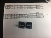
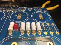
I know I should have followed my original build plan, but I am waiting on a replacement for the C2 caps I mis-spec'ed on my amp boards. So, I started with my Japanese friend, Ishikawa.
All in all, I felt confident throughout.
I chose to use C1. I trust that my Toshiba parts are matched from a trusted source, but I feel it can't hurt even if I don't strictly understand the exact use and how it works. If I gain confidence later, I can always measure the properties and potentially remove it. I also chose to install RV1. I have in my notes to be sure to review the process for the proper setting for initial installation before wiring it up and firing it up along with how to "optimize" later. That should be fun.
No struggles or challenges. My best recommendation is to make sure to read Mark's notes. I would have forgotten to install the JFETs high above the board for potential future use if not
Well, here's the money shots!
Attachments
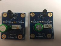
I chose to use C1. I trust that my Toshiba parts are matched from a trusted source, but I feel it can't hurt even if I don't strictly understand the exact use and how it works.
What "trusted source" did you get them from?
Hi Russelc -
I got them from "Punkydawgs" on Ebay. I had it in my notes from one of the threads that Nelson himself verified the source. That's about as trusted as I suppose I can get.
Excellent choice. I have purchased several sets from him. They will be of the tightest matching. You sounded slightly unconvinced...
Russellc
I’ve had a ton of fun over the last few days. There have been a few frustrating moments, but nothing too crazy. So far (knock wood), I can say I took on an appropriate project for my skill level. Enough learning is necessary to make it challenging and fun, but I haven’t had any moments of great despair.
After Ishikawa, I started on the UPS. After making the final decisions of:
• leaving the rectifier sections and smoothing sections of the boards connected,
• no output buffer,
• separate components vs. monolithic rectifiers,
• and yes to the input buffer,
I thought I had everything sorted and all the parts and my build plan ready to go.
I said I’d be transparent about any confusion or issues I had, so here it is. I still don’t know how to choose the right values for the input buffer. I relied on the kindness of @6L6. I’m still researching “Quasimodo”. I may build one of those later and get some proper test equipment, but I just wanted to get on with building a functioning amp. My brain is full for the moment. So, I followed @6L6’s advice to the letter. My values were 0.01uF, 12Ohm and 0.15uF to pair with the Antek AS-4218 transformer. In my BOM consolidation for my parts order, I mistakenly lumped the 0.1uF for the output buffer cap together with my line item for the 0.01uF caps for the input buffer. I wound up with several 0.1uF with no home, and I lacked the 0.01uF caps. I had to order more parts. I also accidentally ordered 1/4W instead of 1/2W resistors for RS1 and RS2. Oops. Make your list and check it twice… or three times…
For those that choose to go with the output buffer - I wasn’t sure, so I ordered the parts just in case. I went with the same brand and style of 3W resistors pictured in the build guide for R1-R8. They will not fit sitting flat to the board in the space for R-11 and R-12. The spacing there is roughly ½”. Just a precaution for those that may choose to put in the output buffer.
Onto the build. @6L6’s build guide is fantastic per usual. It’s nothing too challenging build-wise, IMO. As a noob, I double / triple checked the orientation of the LEDs. The schematic is clear and the traces are simple to follow. However, it’s important to know that the flat sides (cathode) points toward R21 and away from R20. The picture in the build guide specifically showing their orientation is mentioned but seems to have been removed. I’m not sure if it’s clear in my photo. Why did I put in the LEDs? I generally assume that someone much smarter than I put them in, even though it’s clear to some that they do “nothing”. Mark was kind enough to help me figure out the proper resistor value. He gave me the answer and an exercise to help me understand. I paused the build before putting in the diodes b/c I am still waiting on one set of the input snubber caps.
Next – separate components or monolithic rectifier? I chose separate components. There was a mention that separate components on adjoining boards may perform a wee tad better than monolithic rectifiers connected by point to point wiring, so I put it in my build notes. I know that Mr. Pass himself used monolithic rectifiers in some of his amps. Who knows? If other newcomers go this route, the discussion of heatsinks comes into play. There seem to be good reasons both pro and con. If you use heatsinks, the discussion will arise as to whether the diodes need to be electrically isolated from the heatsinks. Then… you get to choose your method. I thought I was being smart by ordering an assembly kit from the same company that manufactures the heatsinks. It comes with a mica insulator. I incorrectly thought the mica insulator acted for both heat transfer and electrical isolation. @6L6 to the rescue again. He said ditch the micas and use “goop”. So, I disassembled the assemblies, removed the micas, and added some non-electrically-conductive silicon heatsink paste. WHEW!
tl;dr – before I set my completed assemblies aside ready to be soldered to the board, I made sure I had my input snubber values set in stone. There are other ways to arrange the components, but given standard locations on the board, I wanted to put them in first. So, I needed to know what power transformer I’d be using. Also of note for my consideration was that originally I thought I could swap the power supply between builds. I can, but it will need to always be paired with an Antek AS-4218 transformer. They’re now a set. I’m not trying to get those snubbers out after installing the diodes and heatsinks. I pray I got them correct.
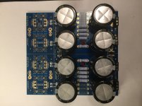
Based on past experience, I made sure I dry-fit all diodes + heatsinks and tightened the assemblies. I installed the caps first. So, I would have had a very hard time snugging the diodes to the heatsinks after installation. Once I get the replacement snubber caps, I can put those in and install the diodes for a complete power supply.
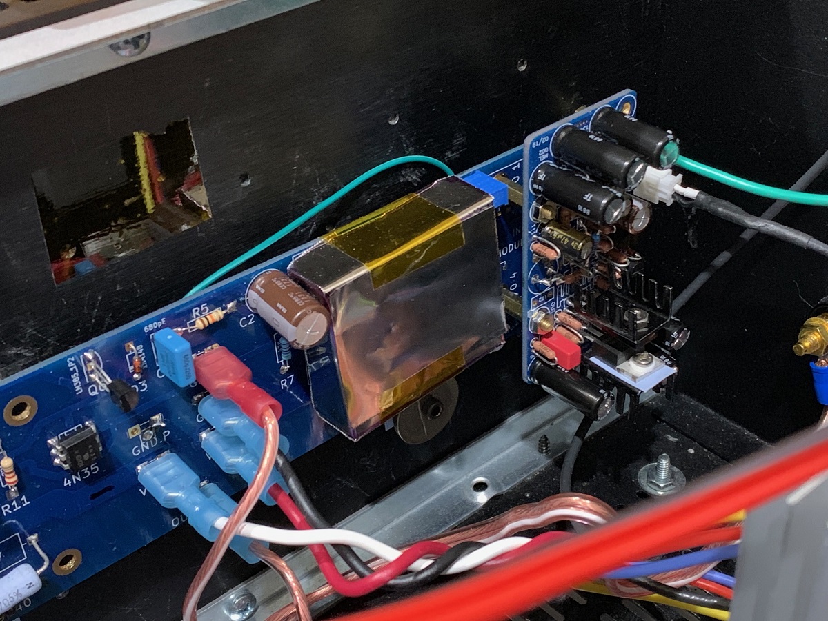
Here are some pictures of the partially assembled power supply. I tried to get tight to one of the LEDs to show orientation. Note – they’re opposite! This is only one side! Check the schematic! Mine could be backwards!
I had intended to do the amp boards next, but no Edcors yet. My order is showing processing/in production
Next up… more IPSs!
After Ishikawa, I started on the UPS. After making the final decisions of:
• leaving the rectifier sections and smoothing sections of the boards connected,
• no output buffer,
• separate components vs. monolithic rectifiers,
• and yes to the input buffer,
I thought I had everything sorted and all the parts and my build plan ready to go.
I said I’d be transparent about any confusion or issues I had, so here it is. I still don’t know how to choose the right values for the input buffer. I relied on the kindness of @6L6. I’m still researching “Quasimodo”. I may build one of those later and get some proper test equipment, but I just wanted to get on with building a functioning amp. My brain is full for the moment. So, I followed @6L6’s advice to the letter. My values were 0.01uF, 12Ohm and 0.15uF to pair with the Antek AS-4218 transformer. In my BOM consolidation for my parts order, I mistakenly lumped the 0.1uF for the output buffer cap together with my line item for the 0.01uF caps for the input buffer. I wound up with several 0.1uF with no home, and I lacked the 0.01uF caps. I had to order more parts. I also accidentally ordered 1/4W instead of 1/2W resistors for RS1 and RS2. Oops. Make your list and check it twice… or three times…
For those that choose to go with the output buffer - I wasn’t sure, so I ordered the parts just in case. I went with the same brand and style of 3W resistors pictured in the build guide for R1-R8. They will not fit sitting flat to the board in the space for R-11 and R-12. The spacing there is roughly ½”. Just a precaution for those that may choose to put in the output buffer.
Onto the build. @6L6’s build guide is fantastic per usual. It’s nothing too challenging build-wise, IMO. As a noob, I double / triple checked the orientation of the LEDs. The schematic is clear and the traces are simple to follow. However, it’s important to know that the flat sides (cathode) points toward R21 and away from R20. The picture in the build guide specifically showing their orientation is mentioned but seems to have been removed. I’m not sure if it’s clear in my photo. Why did I put in the LEDs? I generally assume that someone much smarter than I put them in, even though it’s clear to some that they do “nothing”. Mark was kind enough to help me figure out the proper resistor value. He gave me the answer and an exercise to help me understand. I paused the build before putting in the diodes b/c I am still waiting on one set of the input snubber caps.
Next – separate components or monolithic rectifier? I chose separate components. There was a mention that separate components on adjoining boards may perform a wee tad better than monolithic rectifiers connected by point to point wiring, so I put it in my build notes. I know that Mr. Pass himself used monolithic rectifiers in some of his amps. Who knows? If other newcomers go this route, the discussion of heatsinks comes into play. There seem to be good reasons both pro and con. If you use heatsinks, the discussion will arise as to whether the diodes need to be electrically isolated from the heatsinks. Then… you get to choose your method. I thought I was being smart by ordering an assembly kit from the same company that manufactures the heatsinks. It comes with a mica insulator. I incorrectly thought the mica insulator acted for both heat transfer and electrical isolation. @6L6 to the rescue again. He said ditch the micas and use “goop”. So, I disassembled the assemblies, removed the micas, and added some non-electrically-conductive silicon heatsink paste. WHEW!
tl;dr – before I set my completed assemblies aside ready to be soldered to the board, I made sure I had my input snubber values set in stone. There are other ways to arrange the components, but given standard locations on the board, I wanted to put them in first. So, I needed to know what power transformer I’d be using. Also of note for my consideration was that originally I thought I could swap the power supply between builds. I can, but it will need to always be paired with an Antek AS-4218 transformer. They’re now a set. I’m not trying to get those snubbers out after installing the diodes and heatsinks. I pray I got them correct.
Based on past experience, I made sure I dry-fit all diodes + heatsinks and tightened the assemblies. I installed the caps first. So, I would have had a very hard time snugging the diodes to the heatsinks after installation. Once I get the replacement snubber caps, I can put those in and install the diodes for a complete power supply.
Here are some pictures of the partially assembled power supply. I tried to get tight to one of the LEDs to show orientation. Note – they’re opposite! This is only one side! Check the schematic! Mine could be backwards!
I had intended to do the amp boards next, but no Edcors yet. My order is showing processing/in production
Next up… more IPSs!
Attachments
Last edited:
- Status
- This old topic is closed. If you want to reopen this topic, contact a moderator using the "Report Post" button.
- Home
- Amplifiers
- Pass Labs
- A Noob's First First Watt - M2x