Hello everyone,
Newbie here trying to tackle to the F5. With ACA experience I thought I would take the plunge.
Different versions and lack of step by step guidance has slowed my progress considerably.
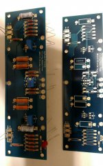
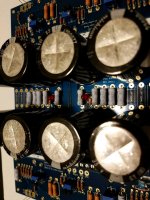
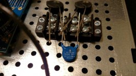
Working on the PCB now and was wondering if someone could give me the go-ahead. I know I still need a 15 k resistor for the led.
Thanks
Newbie here trying to tackle to the F5. With ACA experience I thought I would take the plunge.
Different versions and lack of step by step guidance has slowed my progress considerably.
Working on the PCB now and was wondering if someone could give me the go-ahead. I know I still need a 15 k resistor for the led.
Thanks
Attachments
 ass Labs Amplifiers
This is the guide that you should be reading.
An illustrated guide to building an F5
An illustrated guide to building an F5
There is this updated guide to with new pics
Firstwatt F5 amplifier v3 - diyAudio Guides
I was in the same boat as you when I built mine. My only experience with anything was the ACA so the F5 was a big leap.
The confusing part for me was that all the guides had different information and different version of amplifier and PSU boards, so it was hard to figure out what was correct and what was out of date.
I personally used a combo of three guides. First the PDF one I think you referenced already. That had great instructions on the PSU and other things.
Second, the build guide on this forum by 6L6 - An illustrated guide to building an F5
Then the link I provided above.
The PDF guide had really good instructions on the biasing process, at least the best that I could understand, but it said to turn the adjustment pots one way to set resistance but that was the wrong way so I almost fried my amp.
Use a bulb test for sure, it saved me from certain destruction twice.
Last edited:
The PDF guide had really good instructions on the biasing process, at least the best that I could understand, but it said to turn the adjustment pots one way to set resistance but that was the wrong way so I almost fried my amp.
Use a bulb test for sure, it saved me from certain destruction twice.
Unfortunately going by direction is not fool proof since it also depends on
the orientation of the pot.
Instead, for the V3 schematics,
( see p2 of http://www.firstwatt.com/pdf/art_f5_turbo.pdf )
just turn P1 and P2 so that the measured resistance
across R5 and R6 are close to zero.
Thanks Mr Shaz. Yes I’m in the boat and concur.
Using the pdf guide you linked, authored by 6L6, as it is the most clean and concise, also using the current pcb boards offered by the DIYAstore.
Wanted to follow the thread you and Colin referred to but alas, off the bat, had an older pcb.
So, Mr Shaz, sounds like I am good to go with your first link ( pcbs and ups) until I get to some point to point wiring where the illustrated guide help as well.
Zen mod - hit your link and never saw that page before. Picking up some interesting things there....
Am I building the F5 version 3?
Thanks again for everyone’s great advice and info!
Last edited:
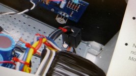
 - ferrite beads
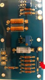
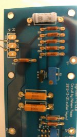
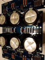
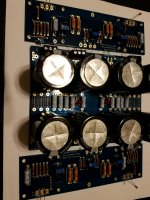
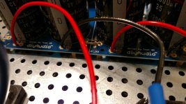
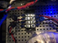
Update. Boards completed. Only question was which direction to mount LEDs, particularly on the PCB for UPS. Please chime in if you see anything faulty or questionable . Thanks
Attachments
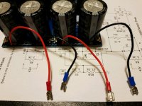
Here is what I did on mine. If you read this thread you can see what I did the first time and the mistake I made doing it the wrong way ->>> An illustrated guide to building an F5
Attachments
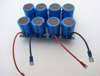
Thanks for the thread cue. Great idea to thread the leads in with the connect crimp, maybe solder after for insurance.
Glad the other holes will still work, hate to redo it
Was hoping not to proceed with the bulb testing. Have no idea how to set that up ... Sounds like another project?
Thanks again for the valuable input 👍😊
Glad the other holes will still work, hate to redo it
Was hoping not to proceed with the bulb testing. Have no idea how to set that up ... Sounds like another project?
Thanks again for the valuable input 👍😊
- Status
- This old topic is closed. If you want to reopen this topic, contact a moderator using the "Report Post" button.
- Home
- Amplifiers
- Pass Labs
- Newbie help with F5