Here is a follow up question concerning % of SOA used as a bias point for PL amps.
I own a gorgeous Aleph30. Per the schematic, the source resistors are 0.47 ohm with 0.25V across the resistor giving 0.531A per transistor.
At 24.75v across each transistor, the power dissipation per transistor is roughly 13.16W.
The Harris IRF244 datasheet claims 125W dissipation.
So, the % of maximum dissipation used in circuit is about 10% for each transistor.
Is that the intent to use around 10% of the nominal datasheet dissipation for each output device? My guess is that 10% keeps the device far enough away from the problematic SOA area.
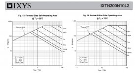
Ixys has a line of big die devices categorized "extended FBSOA" designed for linear operation such as the IXTK22N100L. Other big dies outside the line exhibit some "electro thermal instability" within the SOA on linear mode. Similar problem could be the reason why Bob Cordell avoids trench mosfets for amplifier use while Hugh Dean and Paul Bysouth recommend gate to drain RC shunts to prevent oscillation on high gm Fairchild mosfets.though, someone found some worthy of implementation
Ixys has a line of big die devices categorized "extended FBSOA" designed for linear operation such as the IXTK22N100L. Other big dies outside the line exhibit some "electro thermal instability" within the SOA on linear mode. Similar problem could be the reason why Bob Cordell avoids trench mosfets for amplifier use while Hugh Dean and Paul Bysouth recommend gate to drain RC shunts to prevent oscillation on high gm Fairchild mosfets.
Thanks for this info. It looks like this series has part numbers ending in L2.
Here is one from that series. The 25 deg C dissipation is 800-ish watts and the 75 deg C dissipation is 400-ish watts. What I am thinking at this point is to acquire some parts and lash up a standard Aleph at 1A as Nelson suggested and run it hard for a long time. Then slowly increase the current and see how the amp performs at higher current.
Is there a torture test for the Aleph that would tend to bring on a failure sooner than other tests?
Attachments
SOA Datasheet Test
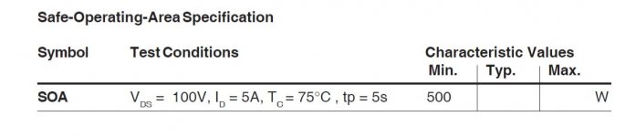
For the part just above, IXTN200N10, here is the datasheet spec for SOA test. 500W, 5A at 100V for 5 seconds.
For a "monster current" Aleph, I would aim for 20V, 5A and 50 deg C heatsink temperature. That would be well inside the datasheet 5-second SOA test.
Is there a link to a spreadsheet for a standard Aleph for bias current and power output at various load impedances?
Aleph Power Spreadsheet
Hi woofertester,
here is the Aleph power spreadsheet") :
:
https://www.diyaudio.com/forums/pass-labs/120646-aleph-3-power-4-ohm.html#post1474323
Posts #3 and #4
Best regards,
Claas
Hi woofertester,
here is the Aleph power spreadsheet
:https://www.diyaudio.com/forums/pass-labs/120646-aleph-3-power-4-ohm.html#post1474323
Posts #3 and #4
Best regards,
Claas
Hi woofertester,
here is the Aleph power spreadsheet
https://www.diyaudio.com/forums/pass-labs/120646-aleph-3-power-4-ohm.html#post1474323
Posts #3 and #4
Best regards,
Claas
Got it. Thanks. It is interesting to try different rail voltages and bias settings.
Ixys has a line of big die devices categorized "extended FBSOA" designed for linear operation such as the IXTK22N100L.
We go back to post 19:
In the Ixsys, they have solved it as follows:
"Every transistor cell is designed with a ballast resistor at the source
to limit its current."
We go back to post 19:
In the Ixsys, they have solved it as follows:
"Every transistor cell is designed with a ballast resistor at the source
to limit its current."
If the IXYS devices are an array of parallel cells with each cell having a source resistor, the device is similar to the array of devices each with a source resistor in the large PL amplifiers. Is this a reasonable analogy to draw?
For the IXTN200N10L2 in particular, the RDSon is 11 milli-ohms indicating that there are so many cells in parallel, that the effective source resistance, while not zero, is vanishingly small.
The IRF244 in my Aleph30 has an RDSon of 0.24 ohms typical. Would it be fair to compare the IXTN200N10L2 to a quantity of the IRF244 in parallel?
If the IXYS devices are an array of parallel cells with each cell having a source resistor, the device is similar to the array of devices each with a source resistor in the large PL amplifiers. Is this a reasonable analogy to draw?
As there are more things going on than real estate, so I don't expect
everything to scale linearly, but the comparison is reasonable.
As there are more things going on than real estate, so I don't expect
everything to scale linearly, but the comparison is reasonable.
Understood. There may be one or more "gotchas" that do not scale. I would guess that having heat spread over 20 pcs of IRF244 creates less of a concentrated hot spot than all of that heat going through one monster IXYS part.
- Status
- This old topic is closed. If you want to reopen this topic, contact a moderator using the "Report Post" button.
- Home
- Amplifiers
- Pass Labs
- Hockey Puck Aleph