Frank, Nelson, others -
Thanks for your work on this project. I'm considering moving my LXmini+2 setup from a MiniDSP 4x10 HD to this ASP. I'm also considering upgrading from the LXmini+2 to LXstudio.
Here's my question. The LXstudio and LXmini+2 specify different crossovers, not just different levels. They have different high-pass filters and different equalization parameters. Even the midwoofer high-pass crossover is different between LXstudio and LXmini+2.
I know the ASP is a new design that doesn't precisely match Siegfried's DSP filters, but: is the ASP designed to mimic LXstudio or LXmini+2? I know the answer is technically "both", since both are supported, but is it designed to replicate one or the other?
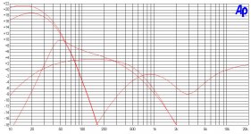
The filter topology for the LxMini is the same, but there are adjustments
in the values. Attached are the curves to the filters I worked up, and you
can play with the LXmini values a bit to duplicate them. You will note that
the high pass filter for the LxMini remains unchanged, and you can also
see the original Lxmini woofer filter for comparison.
in the values. Attached are the curves to the filters I worked up, and you
can play with the LXmini values a bit to duplicate them. You will note that
the high pass filter for the LxMini remains unchanged, and you can also
see the original Lxmini woofer filter for comparison.
Attachments
The filter topology for the LxMini is the same, but there are adjustments
in the values. Attached are the curves to the filters I worked up, and you
can play with the LXmini values a bit to duplicate them. You will note that
the high pass filter for the LxMini remains unchanged, and you can also
see the original Lxmini woofer filter for comparison.
Thanks!
1. Apologies if I'm missing this or if it's a dense question, but in the ASP, is the subwoofer filter designed to match the LXmini+2 filter or the LXstudio filter? They're a bit different.
2. The curves in this chart aren't labeled; is this comparing the DSP to the ASP? If so, which is which, and is the DSP curve the LXmini+2 version or the LXstudio version?
Recently finished soldering the balanced kit from Frank as well. I was surprised at the difference between it and the miniDSP 2x4. So much so I went back to the miniDSP configuration after a day or two listening to the ASP to check whether I wasn’t just falling victim to expectation bias. Even reloaded and double-checked the miniDSP file. Not that Minis had sounded bad before. The top end with the ASP is noticeably more resolving. It’s not a cheap option but it’s definitely a worthwhile one, I think. Used a TI TSP7A-based linear power supply on the ASP, FWIW.
Echoing the kudos above, nice job Nelson. As usual. My diy life would be considerably less rewarding were it not for your alchemy.
Incidentally, my board is labeled 2019 and does not have the ‘Sub’ silk screened above the filter pin.
Echoing the kudos above, nice job Nelson. As usual. My diy life would be considerably less rewarding were it not for your alchemy.
Incidentally, my board is labeled 2019 and does not have the ‘Sub’ silk screened above the filter pin.
I recently purchased the 3-way ASP kit from Frank and have one question I'm hoping someone here can answer for me...
I have the LX Studio setup and was previously using the miniDSP 4x10HD for crossover/eq duties. With the switch to the ASP, do I need to reverse the wiring on the full range driver and dual subs to mimic the phase inversion that the miniDSP program had?
I have the LX Studio setup and was previously using the miniDSP 4x10HD for crossover/eq duties. With the switch to the ASP, do I need to reverse the wiring on the full range driver and dual subs to mimic the phase inversion that the miniDSP program had?
I think so.
Thank you Nelson. One more question... can the 3-way ASP be run as a mix of balanced and unbalanced, i.e. balanced xlr inputs with unbalanced RCA outputs?
I think so.
Also I asked Frank the same question regarding inverting the phase and received this response: "Externally, leave everything straight, the XO has the reversion integrated."
So you are saying I should invert the phase by switching the wiring to the speakers, Frank is saying I don't need to invert the phase because this function is integrated into the ASP.
Does anyone know which is correct?
Wow, the silence is deafening on this thread! I am posting this information here as a sort of "warning" to those considering a purchase of the 3-way ASP for your LX+2 or LX Studio that even if you purchase a completed ASP from Frank, this will be a DIY project because it likely will not be correct when you receive it.
I found out through much of my own research and experimentation that the 3-way ASP as Frank sent it to me was not wired correctly on two different fronts:
1) none of the XLR jacks had their pin 1 connected to the chassis, so they were effectively ungrounded. As is listed in the documentation sent to me by Frank "Connect all XLR plugs #1 directly to XLR plug housing (and by this to the case)." Frank insisted that the plugs were grounded simply by virtue of being mounted in the chassis. This was easy to test with with a multi-meter which showed that they were in fact not grounded. Even after telling Frank this he failed to offer any solutions. I asked for a refund of the labor I had paid for him to install the XLR jacks since they were not installed correctly. He refused.
2) What is listed in the documentation as an optional ground resistor "RG" was installed in the PCB when I received it. This is described as a solution to ground hum issues caused by rack mounting the ASP chassis, so I'm not sure why it came preinstalled.
These issued resulted in my having to do two things to get this thing to stop humming and run quietly: 1) connect all the XLR jack pin 1's to their own housing using a jumper wire. 2) run an additional ground wire from the PCB ground to the chassis.
I was able to locate one other purchaser of this ASP and they had the very same issues I did. I'm thankful I was able to get their help, otherwise I am not sure I ever would have solved these issues.
I still don't have a clear answer from Frank or from Nelson as to whether the the phase of the FR driver and/or subs needs to be reversed when using this ASP as they are reversed in the miniDSP settings. I've settled on what sounds best (I hate that answer BTW, especially in regards to the FR driver.)
Hopefully this info can help someone in the future.
The crossover was designed so that all inversions are done within the
crossover, as seen in the attached block diagram. This would mean that
the intent is that you operate the amplifiers and speakers as non-inverting.
With regard to the grounding, the board has been designed for flexibility.
It provides connections to pin 1, but whether they are used or not is up to
whoever is assembling it. If they are connected they go to circuit ground.
The attachment of circuit ground to chassis is made through R211, a power
resistor found on the center of the board below the attachment labeled
CHASSIS. The spot for the resistor can be filled by a resistor, a shorting
wire or nothing depending on what works best in a given environment.
Attachments

- Home
- Amplifiers
- Pass Labs
- Balanced 3-way ASP NelsonPass