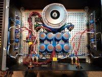
Heck - Sometimes I need to read Zen's stuff a few times to figure out his Wile E. Coyote (genius) shorthand. 
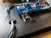
The little thermistors touching the black part of the Mosfet instead of the washer is a belt & suspenders thing - if (somehow) the paint on the end of the NTC becomes worn through and touching the metal, it may ground out, but if touching the plastic, no worries.
Those thermistors, by the way, are there to adjust the Current through the Mosfet (Iq) as the amp warms up.
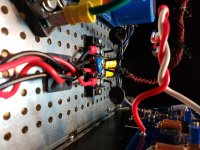
The only thing I see that could be problematic is those ,47R 3W resistors. Usually you don't want those tight to the board because they get fairly warm and having some longer leads and big bends makes it easier to clip probes to.
I do recall reading something about that somewhere but it slipped my mind which ones they were referring to while putting it together. I've had quite a few pics open along with several different threads (plus the build guide pdf) and it gets a tad confusing keeping it straight sometimes.
Thanks for pointing it out so that any others doing their build and perhaps looking here might learn that.
D
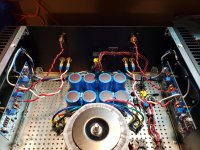
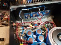
Looking good. I guess you're ready for powering up.
Just a reminder to set P1 and P2 to min value so that the resistance
measured across R5 and R6 are low, to ensure low bias at your initial start up.
Dennis
Thanks Dennis - lefty loosey, righty tighty? CCW to turn to minimum?
And disconnect one amp channel on initial power-up so if you have a symmetrical fatal error you don't kill both sides.
Symmetrical Fatal Error. Sounds like a death metal song. I may use it. Not that we play death metal....
So testing my power supply and coming up with 25V on both sides - give or take point something something - doesn't clear me yet? Was tempted to plug it in this morning before going to work just to see if the LEDs on the amps light up. Glad I didn't I guess.
Last edited:
Thanks Dennis - lefty loosey, righty tighty? CCW to turn to minimum?
Dunno. It depends on the pot and the direction it was installed in.
So best to just turn the pota and measure. Since the pots are in parallel with R5 and R6,
by adjusting the pots you should be able to get the measured resistance
across them down to a few ohms.
We're jamming tonight!!
Welcome to the club. DIYers are the happiest audiophiles I know.

Welcome to the club. DIYers are the happiest audiophiles I know.

Much appreciated good sir.
6l6 - part way down post 2 of this thread / build guide (An illustrated guide to building an F5) there is a rather confusing instructional on how to bias the F5. Interestingly, it says at the outset that "It's the most detailed and informative (and practical)...."
I am by trade a sprinkler fitter, as in pipes and water for fire protection. I've mentioned elsewhere that I follow instructions reasonably well but when there's no pics and phrases like "observe Iq and offset" get thrown about- I get a little nervous (ish). Is there another thread where this is dealt with?
Thx
D
Last edited:
Welcome to the club. DIYers are the happiest audiophiles I know.

They are at first...but eventually they turn greedy and happiness is gone.
Here's a not so minor quibble: I'm at the stage where I would like to Bias my amps. Now after following many of the different threads and the build guide, I have it all wonderfully put together and I come to this:
"1. Turn all variable resistors, P1 and P2 (total of four variable resistors for a stereo
setup) fully counter-clockwise. This can be verified by measuring the resistance
between the outer leads of the variable resistors and it must read zero Ohms."
Really?? I have the boards mounted with the wires all neatly tie wrapped and each of the screws including the ones holding the mosfets threadlocked.... how might one even get at the leads?
Also, there does not appear to be a stop position in these variable resistors. They just keep turning. I don't want to keep turning them but have had all four P1s / P2s well past 25 full turns. Advice please?
When you get to the end of the pots travel (either way) you will hear a faint click.
When you get to the end of the pots travel (either way) you will hear a faint click.
mmmmm. I was waiting for it to actually stop.... perhaps I should turn down Sphongle a tad then!
Gads......Is there such a thing as going too far then???
.... how might one even get at the leads?
It suffices to measure at R5 and R6. One direction on P1(resp. P2) will eventually
get you close to zero ohm across R5 (resp. R6). (The opposite direction
should get you close to 1.5K)
As Kevin mentioned, just listen for the clicking sound to indicate you've
hit the end.
- Status
- This old topic is closed. If you want to reopen this topic, contact a moderator using the "Report Post" button.
- Home
- Amplifiers
- Pass Labs
- Another F5 Build

