MOSFETS ARE MATCHED.
I did this—And it was really really really easy to do. I only fried up one board it would seem. I connected the non-fried one and verified the full rail output on the binding posts...for a split second (did I damage it too????).
Here's the thing—from a NOOB perspective. If this is a hobby that "all people" could benefit from if so inclined to embark upon and explore (I do! Emphatically)—I personally feel that they should be dressed for success and this is why this community is so important—It still boggles my mind that Nelson is on here weighing it—THAT IS SOOOOO RARE—and I'm incredibly grateful—it's exactly like asking a question on a cooking blog and having Martha Stewart answer your question directly. INCREDIBLE). I've learned a lot—and that's why I do things that are consistently way outside a "normal" comfort zone—that's on me—it's all ON me.... However—my experience so far with the overarching concepts of the how these amps go together—was primed with 2x ACA builds and a pioneer B1K build—seemingly perfect.
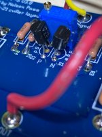
The concept of matching Mosfets was totally missed by me (and apparently at least one other "smart" builder—the ACA doesn't have this concept in it's design). The concept of matching Jfets is hammered all over the place—presumably because the parts themselves are a bit rarefied. The official F5 build guide doesn't include anything about matching Mosfets (if this is on purpose—that's totally fine—I kinda want to know though. And maybe I missed it—If I super zoom in I can see the parts aren't the same—now that I know what I'm looking for). 20/20 tells me, now that I'm looking at the schematic through the smoke and less ignorant eyes, that the Q3, Q4 designations are different—the numbers on the schematic don't match any actual parts designations that I can understand. This has been an incredible learning experience—and I'm not in the least put off—but simply put—was this a builders test? That I basically failed? Haha.
I was totally unprepared for the matching Mosfet conversation (Again, yes I now see N and P on the board—but doods—everyone up here isn't an electrical engineer?). And I have no idea if this ignorance was at the expense of my build.
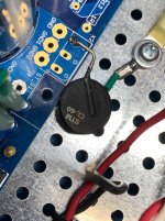
Can I just switch them around and proceed? I clearly smoked R8 on one board—bulb tester confusion there. I don't see anything interesting on any of the other components and they all look new. My PSU to ground connection via CL-60 looks a hair toasty. PSU startup went fine—brilliant actually. Quasimodoed the EFF out of it—bought a scope—had a BRILLIANT time with incredible help—INCREDIBLE, tear jerking help—and learned SO much—and it was a success. (There is one LED that won't light up—and there's no explanation. Swapped the resistor and the LED), the board seems to not like anything at one LED location—connected to a 9V batt I'm getting about half voltage on that LED pad. I'm getting perfect values over V+ and V-. This intensely gets me in touch with my perfectionist tendencies—Light up LED!—I really wanted some inner blue glow.
So... New boards and parts kit? (Truth be told—I don't tend to mess round, like ever, and I've already ordered another full parts kit and boards—not that I'd rather save them for something else [I'm looking at you 9-yr-old daughter]—I mean, I've already got a BOM going at Digikey and Mouser for the AJ—I'M COMMITTED. haha.)? Are my punkydawgs Toshiba's compromised (they look fine)? They were NOT cheap—and the ones on the DIY store were out of stock when I ordered—Did I catch it all in time?????????? I followed what I understood of ZMs beep testing of the Mosfets (no beeps). I verified inner (wiper?) and outer legs of all pots, including P3 (my next foray into another rite of passage). Apparently Jfet testing requires something special and 9V. They visually look new......hmmmmm....
AND BY THE WAY (not yelling—never yelling):
Post #106 (Startup procedures)
Post #109 (F5 biasing Rite of Passage)
By member Dirk (cubicincher)—Should be solidified as THE GOLDEN STANDARD of instructions for both of these processes. I N C R E D I B L Y clear to a "smart" person like me. They should be stickied—copied—etched into nubile stone—and otherwise plastered everywhere.
(Mods let me know If I should post this someplace else.) THANK YOU THANK YOU THANK YOU.
I'm having a great time.
Bingo. One board has 240's, the other has 9240's. They came packaged in pairs that I thought were "matched sets", but were obviously 2 of each item.
Is this the reason I had 23V at the binding posts though? Doesn't seem right.
I did this—And it was really really really easy to do. I only fried up one board it would seem. I connected the non-fried one and verified the full rail output on the binding posts...for a split second (did I damage it too????).
Here's the thing—from a NOOB perspective. If this is a hobby that "all people" could benefit from if so inclined to embark upon and explore (I do! Emphatically)—I personally feel that they should be dressed for success and this is why this community is so important—It still boggles my mind that Nelson is on here weighing it—THAT IS SOOOOO RARE—and I'm incredibly grateful—it's exactly like asking a question on a cooking blog and having Martha Stewart answer your question directly. INCREDIBLE). I've learned a lot—and that's why I do things that are consistently way outside a "normal" comfort zone—that's on me—it's all ON me.... However—my experience so far with the overarching concepts of the how these amps go together—was primed with 2x ACA builds and a pioneer B1K build—seemingly perfect.
The concept of matching Mosfets was totally missed by me (and apparently at least one other "smart" builder—the ACA doesn't have this concept in it's design). The concept of matching Jfets is hammered all over the place—presumably because the parts themselves are a bit rarefied. The official F5 build guide doesn't include anything about matching Mosfets (if this is on purpose—that's totally fine—I kinda want to know though. And maybe I missed it—If I super zoom in I can see the parts aren't the same—now that I know what I'm looking for). 20/20 tells me, now that I'm looking at the schematic through the smoke and less ignorant eyes, that the Q3, Q4 designations are different—the numbers on the schematic don't match any actual parts designations that I can understand. This has been an incredible learning experience—and I'm not in the least put off—but simply put—was this a builders test? That I basically failed? Haha.
I was totally unprepared for the matching Mosfet conversation (Again, yes I now see N and P on the board—but doods—everyone up here isn't an electrical engineer?). And I have no idea if this ignorance was at the expense of my build.
Can I just switch them around and proceed? I clearly smoked R8 on one board—bulb tester confusion there. I don't see anything interesting on any of the other components and they all look new. My PSU to ground connection via CL-60 looks a hair toasty. PSU startup went fine—brilliant actually. Quasimodoed the EFF out of it—bought a scope—had a BRILLIANT time with incredible help—INCREDIBLE, tear jerking help—and learned SO much—and it was a success. (There is one LED that won't light up—and there's no explanation. Swapped the resistor and the LED), the board seems to not like anything at one LED location—connected to a 9V batt I'm getting about half voltage on that LED pad. I'm getting perfect values over V+ and V-. This intensely gets me in touch with my perfectionist tendencies—Light up LED!—I really wanted some inner blue glow.
So... New boards and parts kit? (Truth be told—I don't tend to mess round, like ever, and I've already ordered another full parts kit and boards—not that I'd rather save them for something else [I'm looking at you 9-yr-old daughter]—I mean, I've already got a BOM going at Digikey and Mouser for the AJ—I'M COMMITTED. haha.)? Are my punkydawgs Toshiba's compromised (they look fine)? They were NOT cheap—and the ones on the DIY store were out of stock when I ordered—Did I catch it all in time?????????? I followed what I understood of ZMs beep testing of the Mosfets (no beeps). I verified inner (wiper?) and outer legs of all pots, including P3 (my next foray into another rite of passage). Apparently Jfet testing requires something special and 9V. They visually look new......hmmmmm....
AND BY THE WAY (not yelling—never yelling):
Post #106 (Startup procedures)
Post #109 (F5 biasing Rite of Passage)
By member Dirk (cubicincher)—Should be solidified as THE GOLDEN STANDARD of instructions for both of these processes. I N C R E D I B L Y clear to a "smart" person like me. They should be stickied—copied—etched into nubile stone—and otherwise plastered everywhere.
(Mods let me know If I should post this someplace else.) THANK YOU THANK YOU THANK YOU.
I'm having a great time.
Attachments
Last edited:
Wow pfarrel - step AWAY from the coffee mug!
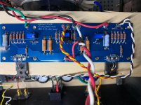
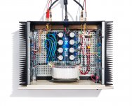
All first world problems right? Like the tidiness sir, nice job. That L bracket on the transformer really helps by giving more space at the back. I couldn't find one, was going to build one, then decided it was fine in the end. After all I've done so far I have enough parts to build another so may go that way in the future. As it is I'm still waiting for my J-fets to show up from punkydawgs to finish up my left channel (Jason didn't have stock at the time) and according to tracking it should be sitting in my mailbox when I get out of here (stuck in Diavik).
Good luck with the rest of it. Please keep on posting here - some of the most helpful people you'll ever want to meet kicking round these forums.
And breathe!!!
Dave
Last edited:
Wow pfarrel - step AWAY from the coffee mug!
All first world problems right? Like the tidiness sir, nice job. That L bracket on the transformer really helps by giving more space at the back. I couldn't find one, was going to build one, then decided it was fine in the end. After all I've done so far I have enough parts to build another so may go that way in the future. As it is I'm still waiting for my J-fets to show up from punkydawgs to finish up my left channel (Jason didn't have stock at the time) and according to tracking it should be sitting in my mailbox when I get out of here (stuck in Diavik).
Good luck with the rest of it. Please keep on posting here - some of the most helpful people you'll ever want to meet kicking round these forums.
And breathe!!!
Dave
Thanks Dave. Yes, 1000% FWP.
These guys have the bracket—Part L-625 $10, bolt and rubber disks:
Toroid Corporation, US manufacturer of Toroidal Magnetic Components
I'm sure they could figure out a way to get it to you as cheaply as possible—or if you have a small brake you could easily make it. They have several sizes, that is the largest and clears the 4U case by 1/4"+ in my build. I raised the perfed inner base plate up by about 1/4" so I could run a power switch under the chassis for a front switch. If you have a 300 or 400VA you don't need the larger size. It fits really well and I could have even moved it farther toward the front w/o touching. I think if I didn't use the L bracket I'd have to break the diode bridge into separate pieces to make a layout. Might do that on the next build!
Yellowknife is on my list for motorcycle journeys.
I will likely do a little desoldering and fire it back up tonight. See what's what.
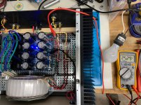
@pfarrell, are you having problems with both channels or just the 1? Just to be sure - you did have it bolted to the heatsink before firing it up? I only ask because it looks like it's sitting on a piece of wood for the picture. R8 does look like it saw some heat but I've done worse and they still live. If you can replace it, it's probably better but you don't actually describe what you are seeing (or did you because I only went back a few posts and too lazy to look now).
You seem to have a bulb tester, what happened when you fired it up?
F5 doesn't need matched mosfets (240/9240) or even matched jfets to fire up successfully and mismatched parts won't cause R8 to overheat.
If dead short + and - output you will eventually burn a few of the smaller resistors though (ask me how I know) but even then it takes more than a minute.
F5 doesn't need matched mosfets (240/9240) or even matched jfets to fire up successfully and mismatched parts won't cause R8 to overheat.
I believe he did what I did and assumed the Mosfet packages came as pairs to install on a channel - one 240 and one 9240 - instead of one package being 240's and the other being 9240's. This does cause some problems
")
D
I believe he did what I did and assumed the Mosfet packages came as pairs to install on a channel - one 240 and one 9240 - instead of one package being 240's and the other being 9240's. This does cause some problems
D
That’s right.
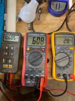
I’ve just now switched them and fired up the left side...Smoked stayed in this time, 0vdc on startup across 3 meters
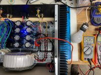
Biasing commences! You can see where i am. Going to 5.9v? It’s a balancing thing like I’ve been reading... little drifty...
Sink is 130-150f, is that high? with only 1.4ishV....
Wait... 0.5V!
Last edited:
Wait...are you measuring about 1.38V across R7 and R8?
If so, that's way too high. You want about 1.3A bias, which translates to roughly
0.6V across those resistors.
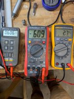
I'm with it now... My schematic DID NOT have the voltage indicated...
Beware. So it was cookin.... only for a few minutes...
Dialed it back...
It Lives!
Biasing was uneventful and fun after I preheated the left side—it's now a "thing"—ultra-fast bias routine. ;-)
Thanks for the support. Listened most of today in less than ideal conditions—Very nuanced amp—clean, refreshing, exceedingly subtle with the right amount of punch—I can tell if a recording is good or not—to me—i.e Adele (she may not be your thing—terrible on digital!, LP a must). Dual ACAs by comparison are not as rich and textured—but they do come off very well at first blush. Kinda insane actually, but they don't have the range or subtleties of the F5. I will plug the F5 in to some more sensitive speakers tomorrow.
Recheck bias after a week or so? Is there a break in period? I think I might have read that someplace....
I expected the F5 to run a lot hotter than it seems to—maybe it's the size of the sinks...It's not cool, but it's cooler than 2 ACAs.
AJ on deck.
Attachments
It Lives!
Biasing was uneventful and fun after I preheated the left side—it's now a "thing"—ultra-fast bias routine. ;-)
Thanks for the support. Listened most of today in less than ideal conditions—Very nuanced amp—clean, refreshing, exceedingly subtle with the right amount of punch—I can tell if a recording is good or not—to me—i.e Adele (she may not be your thing—terrible on digital!, LP a must). Dual ACAs by comparison are not as rich and textured—but they do come off very well at first blush. Kinda insane actually, but they don't have the range or subtleties of the F5. I will plug the F5 in to some more sensitive speakers tomorrow.
Recheck bias after a week or so? Is there a break in period? I think I might have read that someplace....
I expected the F5 to run a lot hotter than it seems to—maybe it's the size of the sinks...It's not cool, but it's cooler than 2 ACAs.
AJ on deck.
Bias should not "break in" or anything. Although it may drift with ambient temp changes. I'd keep an eye on the DC offset...any major changes will show up as changes in DC offset. But in general, it should stay stable.
More bias equals a better sounding amp. So if the amp is cool now, you have an opportunity to increase bias as long as the device temp is under 55-60C or so. Heatsink temps should be around 50C or 25C above ambient.
I have around 115f on the sinks and around 120f on the mosfets. ACAs are around 130f on the sinks.
Should I trying to get the offset closer to zero? It's a delicate thing to achieve as you know.
Under 30mv offset is fine. Under 10mv is really good. Amp will probably drift 10-20mv anyways.
I would shoot for 50C (122F) on the sinks.
Is this the 4U or 5U chassis?
What is the difference between 30mv and 10mv? Is it just "optimal" or does it relate to anything auditory? Also, I feel like someplace I came across a metric for bias setting and heat on the sinks...? We aren't talking a whole lot higher in voltage to achieve 122f (actually might be more than I think seeing my little inadvertent experiment with super biasing.)? Again in your estimation what is "better sounding" with more bias? Thanks!!
What is the difference between 30mv and 10mv? Is it just "optimal" or does it relate to anything auditory? Also, I feel like someplace I came across a metric for bias setting and heat on the sinks...? We aren't talking a whole lot higher in voltage to achieve 122f (actually might be more than I think seeing my little inadvertent experiment with super biasing.)? Again in your estimation what is "better sounding" with more bias? Thanks!!
The difference between 30mv and 10mv of DC offset is not audible. In fact, commercial amps regularly have around 50mv of DC offset.
Bias is voltage across the source resistor decided by the resistor value.
So, at .6V across a .47r resistor you have 1.3A bias...
And you say your heatsink temp is 110F (43C)?
Just bring up the bias (while nulling DC offset) until the amp heatsinks stabilize around 50C (122F). Do this in small steps, letting the amps heat sinks warm up. I think you will find that 1.6A or so of bias will equal 50C.
Typically amps sound more liquid and "heavier" with more bias and the soundstage has more depth. This will depend on the speaker load however. The harder your speakers are to drive the better the amp will sound with more bias. More bias gives you more Class A into low ohm loads.
This is great info. I will keep tweaking. I have around 115f on the sinks depending on where I meter.. goes as low as 112f or so, but not higher than 115f.
And it's a 4U chassis.
My speakers are a pair of Omega Super 3 HO single driver units, made by a fella in CT. 97db, 6ohms. BUT, today I was listening to the F5 where I have been listening to the dual ACAs into a pair of B&W CM1s, 88db, 8ohms close quarters. I also have the B1Korg I made a couple of weeks ago in front for volume control...the source is pretty bad iTunes... no external DAC. In the main system are a couple of turntables I built this year, and a DAC made by the guys at Schitt. And various phono pres (need to build one!), all that said, I can experience the differences between the ACAs and the F5.
The ACA and the F5 are very, very different amplifiers.
Perhaps opposite ends of the spectrum, but a good opportunity for you to see what you like.
I would be interested in why you say this and also very much interested in your whole set up. My source is my computer running JRiver through a 4x10 minidsp into (currently) the ACA for the mids, a very good tripath (there is such a thing) into the tweets and a set of ob subs with their own amps. Killer already but 8m dying to get the F5 in instead of the ACA.
I would be interested in why you say this and also very much interested in your whole set up. My source is my computer running JRiver through a 4x10 minidsp into (currently) the ACA for the mids, a very good tripath (there is such a thing) into the tweets and a set of ob subs with their own amps. Killer already but 8m dying to get the F5 in instead of the ACA.
I do not have the ACA. But the ACA is a low wattage, single ended, single rail design...very simple. Should sound very pleasant but only into 8 ohm or greater, efficient loudspeakers. 2nd harmonic dominant.
F5 is a push pull current feedback amp. Low distortion, more able to drive realistic speaker loads. 3rd harmonic dominant.
I use a f5 turbo to drive a set of 89db/6 ohm 3 ways. Probably not the speaker you would choose to use with ACA.
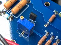
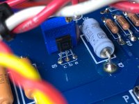
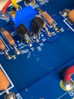
P3 settings
Hi all.
After about just over two months I have finished F5. From searching what to actually order to steps to follow to build PS and amp, looking at the pictures how to assemble the case (worst instructions ever) to biasing the amp I have browsed the threads and posts and found most of the answers i needed. Thank you all help that you provided to others, and me.
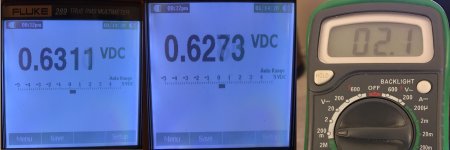
What I still do not know how to do is balance trim-pot P3. What I have done is make resistance over R3 and R4 equal with P3. Should I have made the voltage over R3 and R4 equal instead.
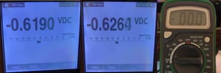
Another question is should I lower the bias voltage closer to the 600mV or are values in the pictures below OK, and how important is it to have bias voltages for left channel close or equal to the bias voltages for the right channel?
Hi all.
After about just over two months I have finished F5. From searching what to actually order to steps to follow to build PS and amp, looking at the pictures how to assemble the case (worst instructions ever) to biasing the amp I have browsed the threads and posts and found most of the answers i needed. Thank you all help that you provided to others, and me.
What I still do not know how to do is balance trim-pot P3. What I have done is make resistance over R3 and R4 equal with P3. Should I have made the voltage over R3 and R4 equal instead.
Another question is should I lower the bias voltage closer to the 600mV or are values in the pictures below OK, and how important is it to have bias voltages for left channel close or equal to the bias voltages for the right channel?
Attachments
- Status
- This old topic is closed. If you want to reopen this topic, contact a moderator using the "Report Post" button.
- Home
- Amplifiers
- Pass Labs
- Another F5 Build