Hi!
I'm hoping to get a bit of advice / help - and yes, I did try searching for answers")
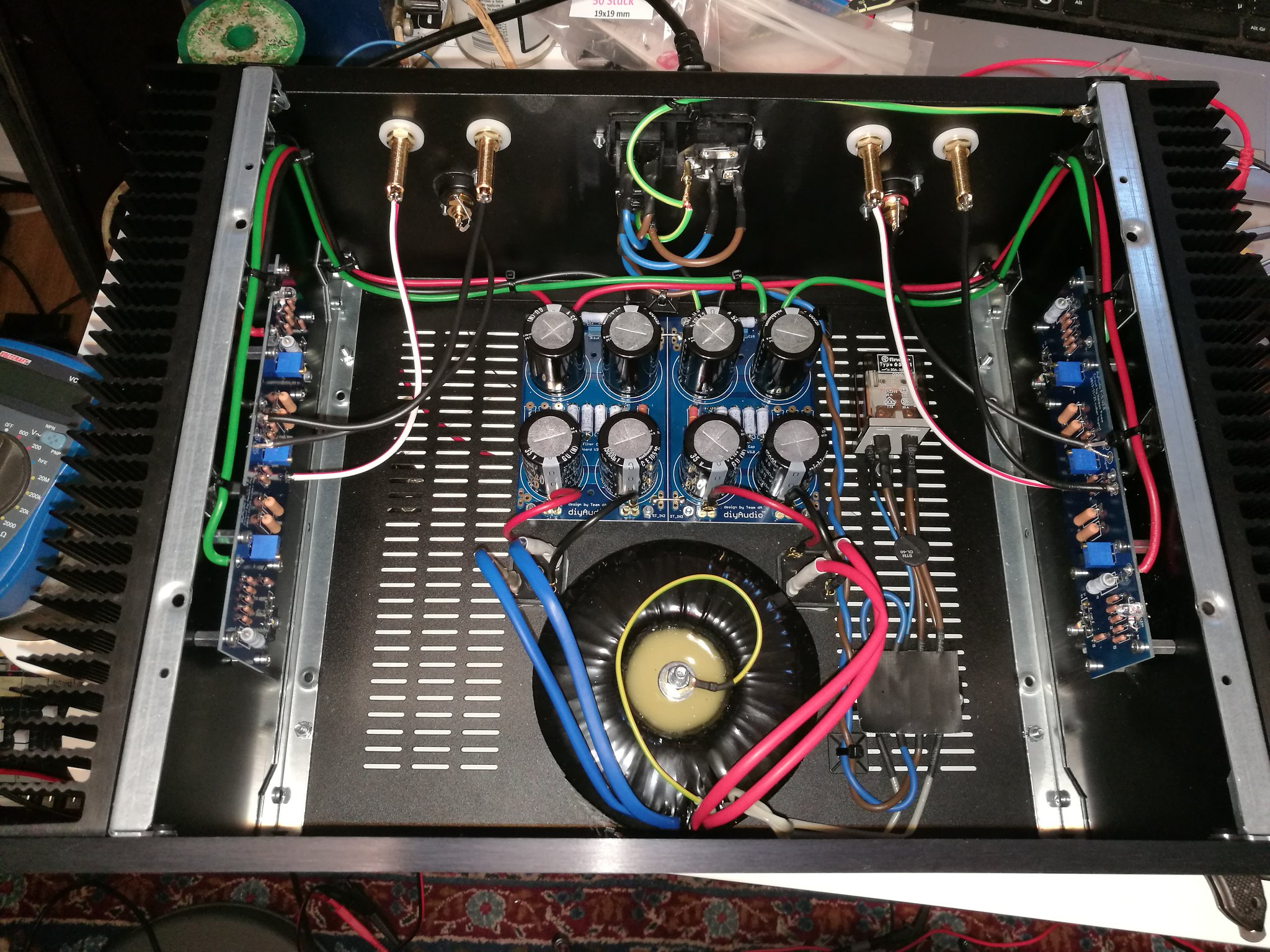
I recently completed the build of two stereo F5s, using the V3.0 boards & kit, the universal PSU boards, Toroidy 400VA 2x18V transformers and Modushop housing.
The amps sound great - I use them to power my co-axial horns - but do hum ever so slightly when input is connected. With no RCA cable connected they're dead quiet.
So, I gather I have a ground-loop issue, and I'm looking to fix it!
To implement a star ground, I'd create a central ground point off the ground on the PSU board, and hook up the speaker negative posts and the ground "supply" to the boards using equal-length and gauge wire. Right? This post then also gets connected to chassis/safety earth via a thermistor.
However, how do I go about connecting the shield/negative of the inputs? At the moment, I'm using regular shielded cable. Would one option be to use XLR-type cable, using the two inner conductors for hot and ground, and just connecting the shield at the board end?
My preamp also has XLR outputs (not true balanced I gather) - would it be of an advantage to use these over the RCA connections?
I'd obviously be grateful for any other advice too!
Cheers
Es
I'm hoping to get a bit of advice / help - and yes, I did try searching for answers
I recently completed the build of two stereo F5s, using the V3.0 boards & kit, the universal PSU boards, Toroidy 400VA 2x18V transformers and Modushop housing.
The amps sound great - I use them to power my co-axial horns - but do hum ever so slightly when input is connected. With no RCA cable connected they're dead quiet.
So, I gather I have a ground-loop issue, and I'm looking to fix it!
To implement a star ground, I'd create a central ground point off the ground on the PSU board, and hook up the speaker negative posts and the ground "supply" to the boards using equal-length and gauge wire. Right? This post then also gets connected to chassis/safety earth via a thermistor.
However, how do I go about connecting the shield/negative of the inputs? At the moment, I'm using regular shielded cable. Would one option be to use XLR-type cable, using the two inner conductors for hot and ground, and just connecting the shield at the board end?
My preamp also has XLR outputs (not true balanced I gather) - would it be of an advantage to use these over the RCA connections?
I'd obviously be grateful for any other advice too!
Cheers
Es
connect one fat wire between left and right pcb GND points , shortest possible
or lift one input gnd with 10R resistor - just insert it between screen and RCA gnd tab
Thanks!
Just to be sure I understand correctly:
Method 1:
Speaker grounds and PSU grounds are atteched to both boards as per standard setup. Additionally there's an extra (fat) wire connecting the two boards?
Method 2:
Speaker and PSU grounds connected as per standard setup, but the shield of one of the inputs is "lifted" with a 10R resistor?
Sorry if my questions are stupid - I'm not very electrially minded, but can "solder by numbers" so to speak
Cheers
Es
Side comment/question - how hot is the STM CL-60 thermistor likely to get during normal operation?
From the photo (top right), it looks like the thermistor is lying on top of the AC mains cabling (could just be skewed perspective). If it's a potential issue, it might be worth making sure that there's a good air gap.
From the photo (top right), it looks like the thermistor is lying on top of the AC mains cabling (could just be skewed perspective). If it's a potential issue, it might be worth making sure that there's a good air gap.
you got it right ......... more than right
mains connected NTC get's hot enough ..... to disturb plastic housing around relay tabs on which ( I resume) NTC is mounted , let alone wires in vicinity of NTC body
NTC must be placed on massive enough pads ( connection block or pcb , whatever it is) to endure heat of NTC legs
remember - never try NTC temp with finger ....... especially when amp is connected with mains

Side comment/question - how hot is the STM CL-60 thermistor likely to get during normal operation?
From the photo (top right), it looks like the thermistor is lying on top of the AC mains cabling (could just be skewed perspective). If it's a potential issue, it might be worth making sure that there's a good air gap.
Hi!
The thermistor up at the mains wiring is just the one for the ground - that shouldn't get hot!
I built-in a kind of soft-start using a thermistor and a relay, which is positioned between the PSU and the right amp board.
Es
What is this wire? Probably better to ground it outside of the toroid regardless.
I'm not sure what the wire is exactly - my Polish is somewhat lacking
- but I think it's a shield.I did try disconnecting it, but that didn't help...
I'll open up the amps in the next couple of days and see what can be done!
Thanks for all the input guys!
Es
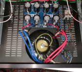
I have an almost identical build with the exact same issue, though my hum is considerably louder coming out of the channel on the left side of the attached picture. I quickly tried adding a 10R resistor between the input RCA jack ground and input wire screen on that louder input. The result is that hum on the side with the resistor is louder, but the hum in the other channel is completely gone.
Since initially building the F5, I have replaced the transformer, soft start, and diodes; but haven’t made any progress in eliminating the hum. I don’t think anything was wrong with the originals.
That said, I now have everything I need to migrate to a dual mono PSU, which I am thinking of putting in a separate chassis.
I’ve inspected every angle of the louder humming channel (again, left in this picture) but I can’t see any bad solder joints or anything suggesting it’s not wired identically to the other channel.
Attachments
I'm not sure what the wire is exactly - my Polish is somewhat lacking
I did try disconnecting it, but that didn't help...
I'll open up the amps in the next couple of days and see what can be done!
Thanks for all the input guys!
Es
I'd expect that it's the transformer's electrostatic shield earth wire. Ensuring that you've got a "Star Ground" earthing arrangement reputedly helps to avoid hum.
Info like this could possibly help:
Earthing (Grounding) Your Hi-Fi - Tricks and Techniques
Hi again,
I'm going to try star-grounding the amp in the following way (unless you guys tell me otherwise):
Star Ground point will be a post isolated from the housing using a CL-60 thermistor. This post attached to:
1. PSU board ground
2. F5 board grounds
3. Speaker negative posts
4. Input terminal grounds.
All using equal length wire.
The inputs signal tabs will be connected to the boards with coax wire, with the shield only attached at the board end.
Will that work in theory?
Cheers
Es
I would probably do a bit more testing before rewiring the whole thing - your wiring looks quite clean and it would be a shame to waste a lot of time if the issue is somewhere else.
Few questions:
Is you green/yellow wire going straight from the EIC to gnd on psu and chassis? You may have a ground wire loop with your preamp. Common solution is to use a bridge between psu gnd and chassis.
Have you tried different sources, preamps etc? I like to test with a phone/ipod (battery operated) straight into the amp with no preamp - might be a good idea to use test speakers. Also try with one channel at a time with the other shorted.
Twist your wires, especially output and input (separate twists).
I have the exact same issue with my F5.
Moving around the input cabling as well as psu cabling makes it better or worse depending where they go...
As soon as i fit the top lid its worse again.
- 10R on one input shield made it perfect for the other channel but the one with resistor gets worse.
- Fat cable between board gnd’s didn’t help either.
Any more ideas would be greatly appreciated
Thanks
theRog
Hahaha - I found a way to minimise the hum to a minimal value (only heard when ear right in front of tweeter)!
Routing the psu cabling tight together with the input signal cable put the hum to a rest
After reading tons of posts (funny enough in thread for F7 post #130ish) where someone theoretically asked about the possibility of a ground loop between the two rca connectors, amp boards and psu board cabling...
I guess he was right about that.
Maybe others haven’t got this because of the following reasons:
a) use of shielded transformer
b) transformer vertically mounted
b) original firstwatt amp board where input and output are on same end ie right where the connectors are
c) routing of input/psu cables nicely along each other because it looks better
Anyone?
Glad i figured it out ;-)
Cheerio theRog
I see in the pictures of your completed amp on the power supply board you have the points labeled gnd,gnd1,gnd2,gnd3,gnd4,gnd5 jumpered together which is correct.That point should go to your amp boards as well as thru a CL60 then to the 120Volt power ground.Then on the diode bridge end of the boards you have those same points (D-1 and D+2) jumpered together again so you have created a loop,remove that jumper,you only need the gnd,gnd1 etc. point jumpered together.
- Home
- Amplifiers
- Pass Labs
- F5 V3.0 Help with Hum Issue