I just remembered there was this discussion back in 2017 about phase splitter on Hybrid amp thread starting from post #108.
I just remembered there was this discussion back in 2017 about phase splitter on Hybrid amp thread starting from post #108.
Hello Indra1
Thank you for the thread link. From a cursory reading, it appears that inter-winding capacitances can cause a resonance that leads to distortion. The inter-layer copper purports to reduce the capactitances. This sounds similar to low current triax cables that have a buried guard sometimes called an inner shield. It reduces current leakage and has a side benefit of reducing the apparent capacitance of the cable when driving the cable.
I will have a go at running an impedance sweep of the transformers unloaded and loaded.
Your loosing the benefit of a balanced source, but if you must split the signal into balanced I’d probably go with opamps. You can probably even test it with the edcor’s in the middle if you change the gain stage to line level. So se buffer edcore balanced and if you don’t like the flavour go back to se gain stage balanced. IMHO Good transformers are expensive and your money would be better spent on a balanced source.
I also would like to quote the Wizard from his 2010 art_arch_nemesis.pdf related to the development process of the M2, F6 and others.
"I have spent quality time with coupling transformers before, but I had never really warmed up to them, possibly because I had not yet reached the 10,000 hour level of listening required to achieve audiophile expertise. In any case, a couple years ago I began experimenting with transformers to solve some problems in a couple of future Zen amplifier projects, and got some fairly good results (good enough for Zens, anyway). Having worked out some circuits, I acquired an assortment of transformers and began evaluating their performance with an eye toward picking the best one. They represented a wide range of cost and materials, and some clearly measured better than others, but when I listened to them I found myself drawn to the sound of one that didn't measure so well.
The dissonance that measures bad/sounds good created called for an unbiased test. So I built two identical amplifiers except for transformers – the very expensive one which measured best, and the unpretentious one that didn't measure so well. I packed them off for a reliable blind test with Joe Sammut, who has 10,000 hours more listening time than me.
“This one is really musical, and that one is not very good.”
Well, that's another data point – a transformer that measures better loses to one that does not. Perhaps if my French was any good, Hiraga would have explained it to me long ago."
I also would like to quote the Wizard from his 2010 art_arch_nemesis.pdf related to the development process of the M2, F6 and others.
"I have spent quality time with coupling transformers before, but I had never really warmed up to them, possibly because I had not yet reached the 10,000 hour level of listening required to achieve audiophile expertise. In any case, a couple years ago I began experimenting with transformers to solve some problems in a couple of future Zen amplifier projects, and got some fairly good results (good enough for Zens, anyway). Having worked out some circuits, I acquired an assortment of transformers and began evaluating their performance with an eye toward picking the best one. They represented a wide range of cost and materials, and some clearly measured better than others, but when I listened to them I found myself drawn to the sound of one that didn't measure so well.
The dissonance that measures bad/sounds good created called for an unbiased test. So I built two identical amplifiers except for transformers – the very expensive one which measured best, and the unpretentious one that didn't measure so well. I packed them off for a reliable blind test with Joe Sammut, who has 10,000 hours more listening time than me.
“This one is really musical, and that one is not very good.”
Well, that's another data point – a transformer that measures better loses to one that does not. Perhaps if my French was any good, Hiraga would have explained it to me long ago."
It would be interesting to know exactly what did not "measure good".
I have a suspicion that there are possibly more subtle measurements that could explain why one transformer would be more musical than another.
As an example, in the loudspeaker domain, subwoofers specifically, flat frequency response of the bottom octave does not tell much about the quality of the bass. A better measurement is the group delay. A tall narrow peak in group delay indicates a possibility of a boomy one-note experience when listening.
Or simply taste. Now have a good time with the project Brian.")
Will do. Thanks for joining the discussion and contributing some very thought provoking ideas.
cheers
".........good enough for Zen........."
oh yeah , good xformers are really good enough for Zen

For those interested, I powered up one of the buffer boards, a signal generator and a scope.
I used +/- 10V supplies and +/- 24v supplies. No significant difference in behavior that is supply dependent.
Applying 1V AC p-p, the -3dB high frequency point is 1.72 MHz. At the low end, the output is 0dB down at 1Hz. That is as low as my sig gen goes.
The output impedance is 470 ohms. Placing a 470 resistor across the output lowers the output to approximately 0.707 V p-p.
These boards could make a nice low cost buffer block for a DIY crossover. It would be spacious and easy to fiddle with RC values. You would have to account for the 470 ohm output resistance.
cheers
Driving 1/2 of the 600 ohm input is the same as driving a 150 ohm load. The 470 ohm output impedance of that buffer is going to push the 3 dB point of LF response pretty high.... Driving 1/2 of the 600 ohm input and measuring across the 15k winding ...
Driving 1/2 of the 600 ohm input is the same as driving a 150 ohm load. The 470 ohm output impedance of that buffer is going to push the 3 dB point of LF response pretty high.
Thank you for the tip. I will measure the buffer driving the transformer and report that here.
I also ordered a couple of differ flavors of the Edcor PC transformers to try. May as well try everything and then decide if there is merit in the approach.
1/2 of 600 ohm tap of PC600-15k
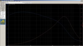
Attached is an iunloaded mpedance/phase plot of 1/2 of the 600 ohm winding of an Edcor PC600-15k transformer.
This winding has a resonance around 3.7 kHz.
The low frequency inductance starts at about 390 mH at 10 Hz and tapers to zero near resonance. At 20 kHz, the capacitance is around 24 nF.
This is from pin 1 to pin 2
Attachments
Last edited:
A couple of the daughter-card mounted buffer stages for the M2x amplifier in the diyAudio Store, have output impedance less than 1 ohm. If building a buffer with extremely low output impedance is important to you, I suggest downloading the schematics and BOM of the "Tucson" and the "Norwood" cards from M2x. They're small, they're simple, and DIY builders report being extremely pleased with their sonic performance.
_
_
Last edited:
- Status
- This old topic is closed. If you want to reopen this topic, contact a moderator using the "Report Post" button.
- Home
- Amplifiers
- Pass Labs
- M2 inspired balanced output preamp idea