Hello everyone.
I made an aca and a boz. I am very satisfied with the performances, but I would have some questions:
1) I read somewhere that aca works better with regulated power supply. My power supply is: 19V transformer for 24V continuous (modified aca), fast Mur820 diodes, 22000uf samwha screw capacitors, and a 2K2 ohmite resistor in short circuit. I ask if you have a scheme of a possible regulated power supply, and what are the advantages compared to my power supply.
2) I put fast diodes on the aca and schotty diodes on the boz. After some listening tests I noticed higher performances (three-dimensionality, soundstage, scanning instruments in space, natural tone without "S" hissing). But I read somewhere that someone prefers slow diodes, I read in an article that even Mr. Pass prefers slow diodes. I kindly ask your opinion on this, especially to understand if I'm on the right track or I'm wrong.
Thank you very much for the answers, and sorry for some uncertainty in the translation with Google translate.
")
A Class A amplifier places different constraints and demands on its power supply (PSU) from the more typical Class A/B amp. The biggest difference is the constant current demand from the Class A amp. Even with a small to medium size amp such as the ACA, the constant current draw will change the relationship between the bridge rectifier, reservoir capacitor, filter resistors and final smoothing capacitors. Each of these parts affects the final voltage, including ripple, that powers the amplifier circuit.
The choice to use a voltage regulator as part of a Class A PSU is also not as simple as it would be for a Class A/B supply. While I am currently working with a set of PCBs that support the use of an integrated regulator (LM1084), I have not installed the regulators yet. Before I do that, I want to better understand how the individual parts of the PSU affect the performance and sound of the amplifier.
One of the issues that I have run into with my recent builds is the voltage loss from the GBPC style chassis mount bridge rectifiers which are commonly used in the FirstWatt and clone amplifiers discussed on these forums. The first build (ACA-220 v1) used an Antek AS-3222 toroidal transformer feeding a 24000 uF reservoir capacitor through On Semiconductor GBPC3504 bridge rectifiers for each channel. This resulted in about 27 Volts at the terminals of the reservoir caps, rather than the 28+ Volts that I was expecting. While 1.0 or 1.2 Volts may not seem like much, it eats into the headroom needed to produce a solid, low ripple 24.6 Volts to the amp.
After some experimentation, I have currently settled on 1.5Ω Ohms for the power resistor after the reservoir cap. This was about the minimum value that still provided good ripple reduction. A value of 2.26Ω yielded lower ripple, but at the expense of lower voltage to the amp. Space on the modified ACA boards permits a pair of 10000 uF, 50V filter caps, with a pair of parallel 0.22Ω resistors before the second of the two filter caps. The 1.6 Amp quiescent current of the modified ACA accounts for the voltage loss through the resistors, and also through the rectifiers. This overall PSU setup seems to be a "sweet spot" for good sound, resulting in an amplifier that is a pleasure to listen to.
It would be possible to alter this setup by eliminating the 1.5Ω power resistor, connecting the reservoir cap directly to the first of the two on-board filter caps, and installing the LM1084 adjusted to output 24.6 Volts. Due to the necessary voltage headroom to ensure that the regulator is not operating at its minimum dropout voltage, the final PSU output voltage is about the same using the regulator with CCRC vs unregulated with CRCRC. I may try the regulator sometime later, but for now I am busy trying other things.
Yes, it is a lot of work to replace a good SMPS.
sorry for the delay but I had several commitments these days.
I read your answers, thank you very much.
I understood that there is no defined power supply, but we need to do some tests.
surfing the net I found this Power supply that is in the picture I attached, what do you think?
I read your answers, thank you very much.
I understood that there is no defined power supply, but we need to do some tests.
surfing the net I found this Power supply that is in the picture I attached, what do you think?
Attachments
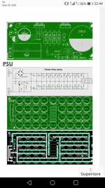
I don't recommend either the amp board or the PSU board that you show. Neither have any advantage, and they both have problems. The amp board is missing R15, which is used to improve performance. The PSU board makes a common assumption that a lot of small capacitors is better than a few large capacitors, which is not true. It just makes a lot of work to solder all the small caps. This PSU board also uses small traces, and a non-optimal routing for what should be a star ground connection.
You should learn to walk before you start to run. I recommend that you buy the ACA kit from the diyAudio store and use the 24V SMPS PSU that comes with it.
You should learn to walk before you start to run. I recommend that you buy the ACA kit from the diyAudio store and use the 24V SMPS PSU that comes with it.
currently my aca is this attachment in photos.
Two Samwha 22000uf per channel, mur820 diodes and a 2K2 Ohmite short-circuit resistor. I'm quite happy with the performance and sound quality.
My question is if by chance there is a Power supply different from mine that can still improve, because the aca deserves it.
Do you think mine could already be a good Power supply, or do you think I have to try some other configuration ??
(PS: do not consider the PCBs of the photo before, I sent the photo only for the PSU)
Attachments
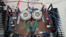
Now that I have seen the picture of your amp, I would agree with 6L6. You are already on the right track with your power supply. There is nothing wrong with a point-to-point wired PSU, which is what you have. Mounting the big filter capacitors onto a PCB can be convenient, but is not always an improvement to the quality of the voltage supplied to your amp.
The biggest improvement you can make to your amp is to build a proper metal chassis for it. The ACA is a good enough amp that it deserves a good chassis. This will make your amp safer by hiding the high voltage wires and connections, and it may also improve the sound by shielding the circuit from outside electrical interference. When you are routing the wires from the PSU caps to the ACA boards, keep them close together, and away from the input wires from the RCA connectors.
The next thing you could try is making the Vdd (positive) connection between the two big caps with two 0.22 Ohm, 3 Watt resistors in parallel. This will give a small 0.11 Ohm connection between the caps and will filter some more of the switching noise from the rectifier diodes.
Try those things (complete metal chassis and filter resistors), and if the amp sounds good to you, congratulations! You are done.
I thank you very much for your availability. I'm glad to know that I have a good Power supply.
as far as the 0.11ohm resistances between the positives of the two capacitors were concerned, I had already thought about it, and the fact that you confirm it encourages me more to try them out.
Regarding the frame of the aca, this photo is just a test wood base, but soon I will mount all the complete amplifier, inside the cabinet of a former Berberer A500, whose sinks are in the picture.
thanks again, you're very kind
this is my boz ..
both in the boz and in the aca I removed the voltage regulation trimmer.
After setting the voltage correctly, I removed the trimmers, I measured the values and replaced them with fixed resistors of the PRP type, the quality improvement was remarkable, the trimmers constitute a dangerous bottleneck, damaging the sound much of more than a poor capacitor.
Attachments
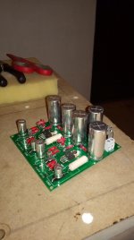
Unfortunately, two schottky diodes were burnt on the boz.
It happened about 15 days ago, and after replacing the diodes this morning it happened again, after about 10 days of perfect operation.
I ask you why this happened. Perhaps it may be that the schottky diodes are "weak" in the ignition pulse to charge the capacitors ??
But anyway there is a 1000uf capacitor immediately after the diodes, and then 4 1000uf capacitors after the stabilized voltage at 60V. So there is not a big capacity !!
But there is no short circuit in the PCB, so the only reason I think is that the schottky diodes are very weak at the impulse, what do you think?
(my schottky diodes are 2A / 600V)
- Status
- This old topic is closed. If you want to reopen this topic, contact a moderator using the "Report Post" button.
- Home
- Amplifiers
- Pass Labs
- Question power supply aca/boz