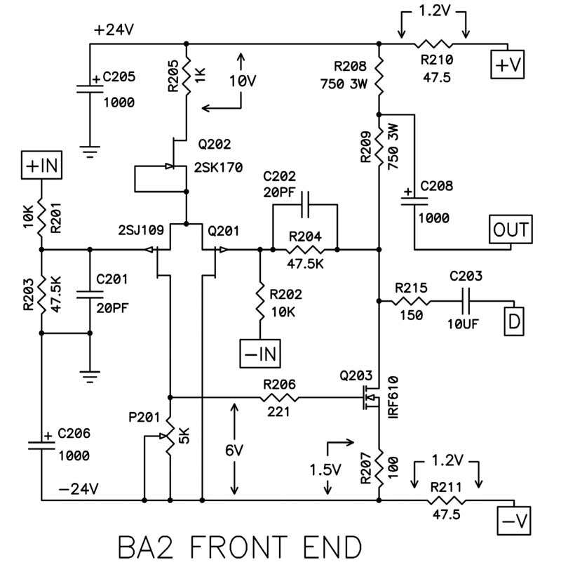
I'm trying to understand this stuff so I'm working through some BA-2 sims.
Let's say I want to double the gain, so I've adjusted R203 and R204 to 100K. (Yes, I know Nelson says you can go all the way to 150K without changing C202, but like I said, I'm trying to understand this stuff.)
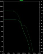
If I run an AC sweep in SPICE with the original values then and probe the VAS output node then I get a -3dB point at about 200KHz with an excess phase angle of a bit less than 45º, which seems to fit well with Cordell's advice of "use 40 and keep 50 in the back pocket".
OK, so back to doubling the gain. With the 100K resistors and the Miller cap unchanged, the -3dB point drops to 80KHz. If I make the same relative adjustment to the Miller cap (to 10pF), then I keep the 200KHz bandwidth, but the excess phase at that point has risen above 50º.
A compromise of 15pF gives me roughly 100KHz bandwidth with a slightly lower excess phase than the original.
Is this a reasonable analysis of the trade-offs, or am I going about this all wrong?
Let's say I want to double the gain, so I've adjusted R203 and R204 to 100K. (Yes, I know Nelson says you can go all the way to 150K without changing C202, but like I said, I'm trying to understand this stuff.)
If I run an AC sweep in SPICE with the original values then and probe the VAS output node then I get a -3dB point at about 200KHz with an excess phase angle of a bit less than 45º, which seems to fit well with Cordell's advice of "use 40 and keep 50 in the back pocket".
OK, so back to doubling the gain. With the 100K resistors and the Miller cap unchanged, the -3dB point drops to 80KHz. If I make the same relative adjustment to the Miller cap (to 10pF), then I keep the 200KHz bandwidth, but the excess phase at that point has risen above 50º.
A compromise of 15pF gives me roughly 100KHz bandwidth with a slightly lower excess phase than the original.
Is this a reasonable analysis of the trade-offs, or am I going about this all wrong?
Attachments
Last edited:
I brushed up on Cordell again, and it looks like I am testing the right point, although probing before and after the LTP might also prove instructive.
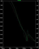
He does mention running all the way out to 200MHz, 'cause you never know what you might find. I get some wobbles and an ugly spike at even higher f (~500MHz), but the peak is at -70dB so the Miller compensation seems to be doing its job there.
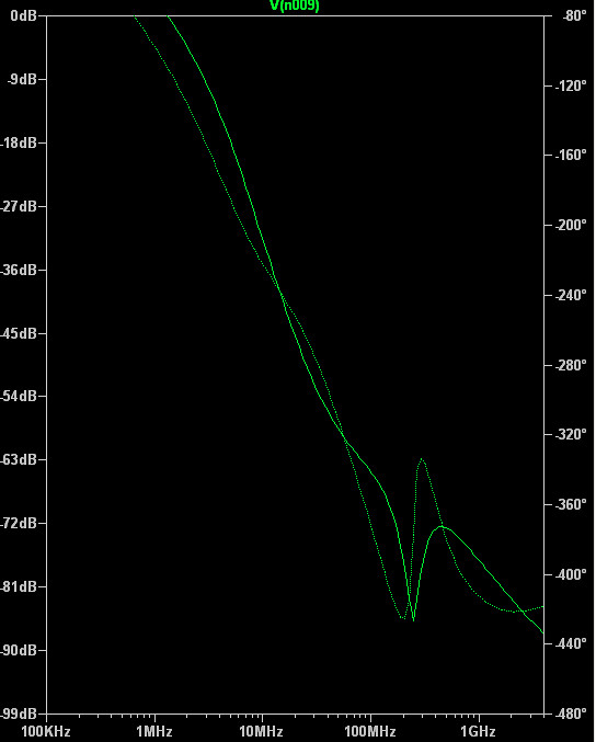
Cordell also mentions phase margin; loosely translated I want to make sure it behaves will with both 1/2 and 2X the Miller capacitance. Things look good down to 4pF, although I start to get a peak at 110KHz if I drop to 3.5pF.

On the upper side we start to see a phase angle bump form at 150pF. I don't know if that's significant or not, but it does foreshadow a gain levelling once things climb above 1nF.

So any of the 10pF, 15pF or 20pF values have plenty of phase margin (assuming I'm looking at the right things).
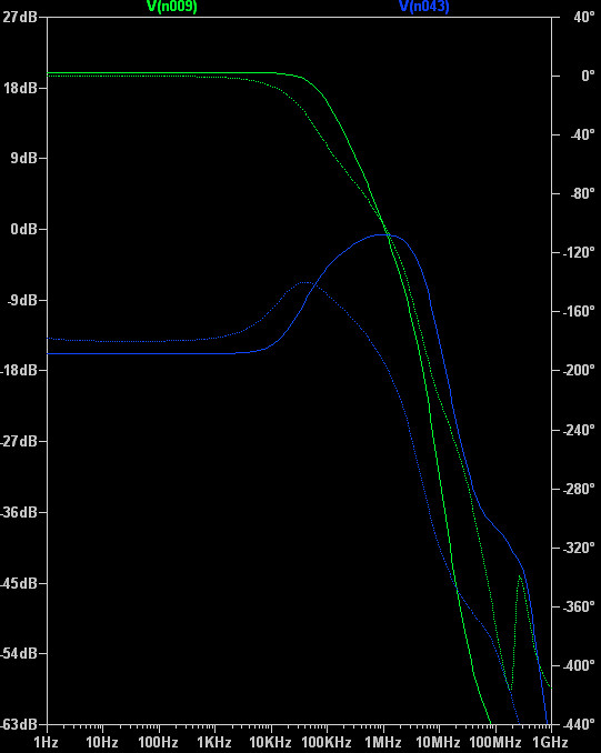
When I measure the output of the LTP (blue trace) I get a hump around 100MHz for all the capacitance values. The hump is about 13dB at 5pF, falling to 8dB at 40pF. This hump is also present in the original, and even larger at 21dB. So I presume it's benign?
He does mention running all the way out to 200MHz, 'cause you never know what you might find. I get some wobbles and an ugly spike at even higher f (~500MHz), but the peak is at -70dB so the Miller compensation seems to be doing its job there.
Cordell also mentions phase margin; loosely translated I want to make sure it behaves will with both 1/2 and 2X the Miller capacitance. Things look good down to 4pF, although I start to get a peak at 110KHz if I drop to 3.5pF.
On the upper side we start to see a phase angle bump form at 150pF. I don't know if that's significant or not, but it does foreshadow a gain levelling once things climb above 1nF.
So any of the 10pF, 15pF or 20pF values have plenty of phase margin (assuming I'm looking at the right things).
When I measure the output of the LTP (blue trace) I get a hump around 100MHz for all the capacitance values. The hump is about 13dB at 5pF, falling to 8dB at 40pF. This hump is also present in the original, and even larger at 21dB. So I presume it's benign?
Attachments
One more crack at this.
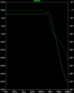
My closed-loop gain is 20dB. If I disconnect the NFB I have a gain of 67dB. That's my closed loop gain, right?
If I then run an AC analysis in SPICE, the output curve starts out at 67dB. So far so good.
It crosses 20dB at 560kHz. Is that my unity-gain point, or do I have to have the feedback enabled to get find the unity-gain frequency?
(Cordell mentions 500kHz as a reasonable unity-gain frequency, so it passes the sanity test.)
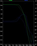
So here are the results of using the LT video method. First you ground the input, break the loop with a 0V voltage source, and then inject your AC analysis through that voltage source:
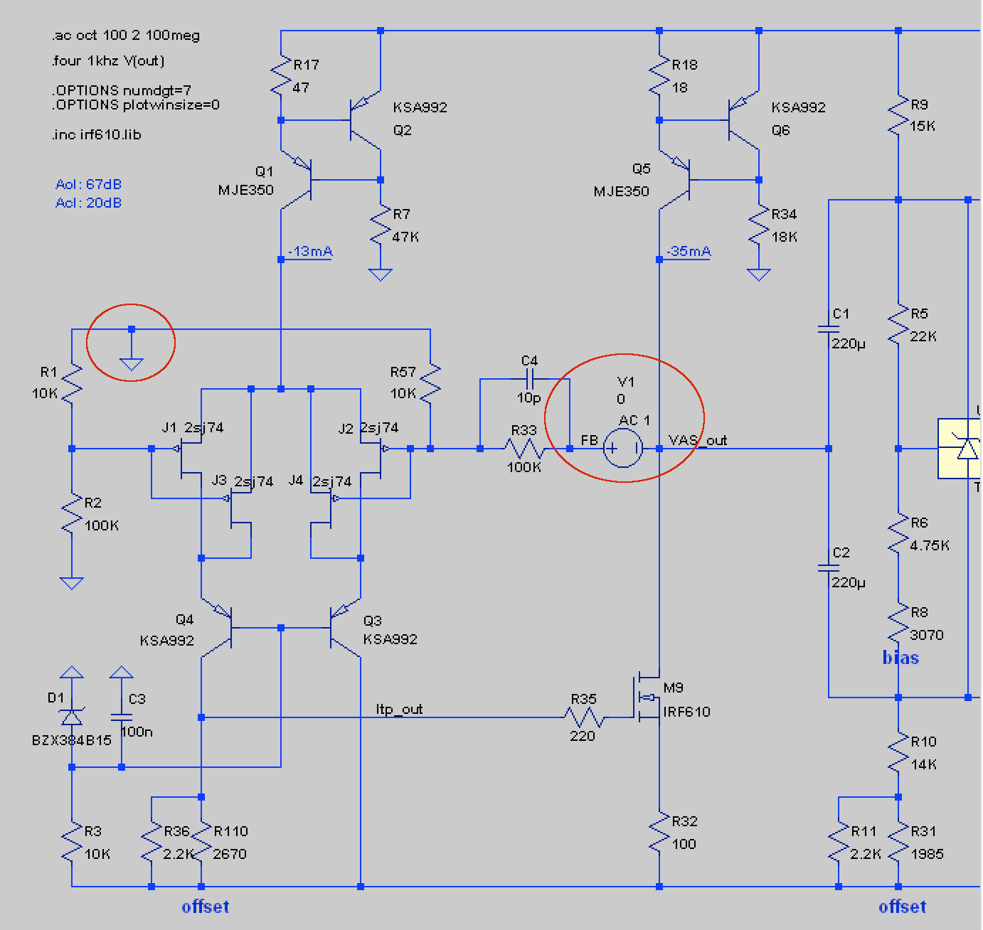
You then plot V(VAS_out)/V(FB) and you can look at the response with compensation changes.
Here are the responses with 10p, 15p and 20p for C4:

Phase margins are 79º, 77º and 75º. Fairly minor differences, as are the bandwidth differences.
You then plot V(VAS_out)/V(FB) and you can look at the response with compensation changes.
Here are the responses with 10p, 15p and 20p for C4:
Phase margins are 79º, 77º and 75º. Fairly minor differences, as are the bandwidth differences.
- Status
- This old topic is closed. If you want to reopen this topic, contact a moderator using the "Report Post" button.
- Home
- Amplifiers
- Pass Labs
- Feedback stability vs gain