Folks:
I'm building an integrated amp for my daughter, consisting of a Bride of Zen (jfet version) preamp and a bridged ACA. I am having trouble with the BOZ and would appreciate some guidance.
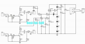
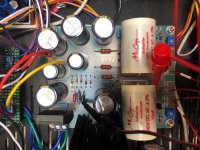
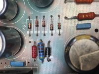
The BOZ pcb was purchased off of ebay (not something I would ordinarily do, but NP's patent on this circuit has expired); the schematic provided by the vendor along with a couple of photos are attached.
Here are what I believe are the relevant readings:
AC = 19.33V
D1 to Ground = 25.2 VDC
R2 to Ground = 11.65 VDC
D6 (Cathode) to Ground = 11.71 VDC
D6 (Anode) to Ground = 7.84 VDC
R3 to Ground = 7.8 VDC
R4 to Ground = 7.8 VDC
This is a learning opportunity for me: my assumption is that the power MOSFET (IRF610) is not functioning properly, but before I tear it out I thought it better to ask the question. Am I on the right path here?
Thank you for your patience and support.
Regards,
Scott
I'm building an integrated amp for my daughter, consisting of a Bride of Zen (jfet version) preamp and a bridged ACA. I am having trouble with the BOZ and would appreciate some guidance.
The BOZ pcb was purchased off of ebay (not something I would ordinarily do, but NP's patent on this circuit has expired); the schematic provided by the vendor along with a couple of photos are attached.
Here are what I believe are the relevant readings:
AC = 19.33V
D1 to Ground = 25.2 VDC
R2 to Ground = 11.65 VDC
D6 (Cathode) to Ground = 11.71 VDC
D6 (Anode) to Ground = 7.84 VDC
R3 to Ground = 7.8 VDC
R4 to Ground = 7.8 VDC
This is a learning opportunity for me: my assumption is that the power MOSFET (IRF610) is not functioning properly, but before I tear it out I thought it better to ask the question. Am I on the right path here?
Thank you for your patience and support.
Regards,
Scott
Attachments

........the voltage drop between gate and source irf610 should be around 4V........
looks good.
4 zener diodes with 4V sum up to 16V........here not.
a zener diode needs a current of 4mA or so (see datasheet). imho you can lower the 4,7k res to 2,2k.........
your 2200uF elcap at the rectifier can withstand 25V ......you measured 25,2V?
i think it is no good idea to combine nelson`s zen amps to a "new schematic".
late night here
......lower the 4,7k res to 2,2k.........
.....
bingo .....
first thing to try
....why I didn's saw that ?

bingo .....
....why I didn's saw that ?
.........because late night here

mjf and ZM:
Thank you! I replaced the 4.7k resistor with a 2.2k and the voltages increased:
R3 to Ground = 10.85 VDC (source)
R2 to Ground = 14.76 VDC (gate),
still a little shy of ideal. I then replaced the 2.2k resistor with a 1.82k and the voltages increased by about 0.25 VDC:
R3 to Ground = 11.11 VDC (source)
R2 to Ground = 15.02 VDC (gate)
Would it be worthwhile to swap in a value lower than 1.82k or is this close enough? The bias has not yet been adjusted and the amp currently sounds pretty rough, but before I move on it seemed wise to verify this issue had been adequately resolved.
Alan4411:
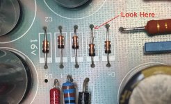
Hmm, I didn't notice that before and it isn't there now. Must have been a piece of scrap. Is it possible the diode is fried? Having changed R1 and gotten the results indicated above, is it advisable to also replace D2?
Regards,
Scott
Thank you! I replaced the 4.7k resistor with a 2.2k and the voltages increased:
R3 to Ground = 10.85 VDC (source)
R2 to Ground = 14.76 VDC (gate),
still a little shy of ideal. I then replaced the 2.2k resistor with a 1.82k and the voltages increased by about 0.25 VDC:
R3 to Ground = 11.11 VDC (source)
R2 to Ground = 15.02 VDC (gate)
Would it be worthwhile to swap in a value lower than 1.82k or is this close enough? The bias has not yet been adjusted and the amp currently sounds pretty rough, but before I move on it seemed wise to verify this issue had been adequately resolved.
Alan4411:
Hmm, I didn't notice that before and it isn't there now. Must have been a piece of scrap. Is it possible the diode is fried? Having changed R1 and gotten the results indicated above, is it advisable to also replace D2?
Regards,
Scott
Alan4411:
Hmm, I didn't notice that before and it isn't there now. Must have been a piece of scrap. Is it possible the diode is fried? Having changed R1 and gotten the results indicated above, is it advisable to also replace D2?
No reason it will have failed. I just wondered if the 'tail' was shorting the diode so you lost 4 volts from the string. Easy to confirm all are well. From ground measure the Cathode of each and you should see, about 4 volts, 8 volts, 12 volts and 16 volts at the top D2...
Alan4411 and ZM:
Yes, the diode string is working properly:
D5 cathode to Ground = 3.81 VDC
D4 cathode to Ground = 7.61 VDC
D3 cathode to Ground = 11.4 VDC
D2 cathode to Ground = 15.2 VDC
I take it this is adequate and R1 can stay as is.
Do I understand correctly that the drains of the jfets to Ground should read one-half of 15.2 VDC (and not 1/2 of the 25.2 VDC at D1)?
Regards,
Scott
ZM:
A green LED has been added to the diode string to great effect:
R2 to Ground (MOSFET gate) = 16.5 VDC
R3 to Ground (MOSFET source) = 12.57 VDC
Reinserting a 2.2k resistor in place of the 1.82k would reduce those readings by 0.25 VDC. Is that recommended?
The readings for the jfets have me concerned:
L ch Drain to Ground = 0.503
R ch Drain to Ground = 0.491
Again, I have not begun biasing yet. But I also did not adjust the 25k pots before installing them; aren't they usually shipped set towards the middle of their range?
Regards,
Scott
25V input to reg
16.5V at mosfet gate
so 8V5 across R1 , in case of 2K2 , that's 3.8mA , which is enough .... leave it as is and forget
damn 25K pots on left side of schematic are volume pots , no setting with them
if you don't have approx. 6V or so at JFet drains , you got fakes
Hasta la Vista , Babe .......... buy again on fleabay , without checking first
wait a moment ....... you didn't tell - from where are your 2SK170?
suffix ?
ZM:
Argh! Okay, so R1 is currently 1.82k, not 2.2k, which means 4.7mA or so.
The jfets were purchased from Alex Weitzman, who sells on ebay using the name "alweit". He also has a presence here and many have spoken highly of him, so I expect his jfets are genuine and were as claimed. I bought several pairs of 2SK170BL from him, all with idss in the 9 mA range, so swapping in a new set is certainly an option.
I can remove and bypass the 25k pots and will report back.
Regards,
Scott
ZM (and mjf and Alan4411):
Okay, to be safe I've replaced the jfets. I did not remove the 25k pots but turned them all the way up, and have left the 1.82k resistor in at R1.
The good news is that there is adequate gain -- the volume knob reasonably correlates to what you might want. The bad news is that the music is weirdly muffled -- there is unexpected distortion. I wonder if my bridging of the ACA boards is incorrect and the culprit. Will post a diagram / photo when I get a chance.
In the meantime, thank you all for your generous support. I was clearly heading off in the wrong direction and very much appreciate the guidance. This hobby continues to be both a trial and an education for me.
Regards,
Scott
ZM & mjf:
Sorry for the belated response; I came down with the flu a couple of days ago and am only now coming out of the fog.
Here are the readings you requested:
Right ch jfet Source to Gnd = 54.9 mV DC
Right ch jfet Drain to Gnd = 0.503 VDC
Left ch jfet Source to Gnd = 55.1 mV DC
Left ch jfet Drain to Gnd = 0.508 VDC
Voltage drop across R10R = 55.1 mV DC
Voltage drop across R10L = 55 mV DC
The value of R7R and R7L is 2.2k
So it's the jfets (again)?
Regards,
Scott
- Status
- This old topic is closed. If you want to reopen this topic, contact a moderator using the "Report Post" button.
- Home
- Amplifiers
- Pass Labs
- Help with BOZ (jfet) Diagnosis