Hi folks
I'm building up a pair of ACA #1 boards and the only parts I don't already have are the IRFP240 MOSFETs.
Should I just buy some IRFP240s or would any of these I already have be suitable:
IRFR214 N-channel MOSFET Transistor, 2.2A, 250V, input capacitance 140pF
FDD8447L MOSFET N-Ch 40V 15.2A, input capacitance 1970pF
IRF640 N-channel MOSFET, input capacitance 1300pF
IRFB4019 MOSFET 17A 150V N-chan HEXFET Infineon Class D Audio, input capacitance 800pF
What might come up with these packages types is dissipation capabilities.
The IRF640 can dissipate 125w, but you are looking to keep it at 25% of max dissipation, which is ~31w. What is the total dissipation of the ACA v1?
The IRFB4019 is 80w total dissipation.
Not that it won't work dissipating more 25% wattage, but the life of the mosfet is shortened.
Perhaps the guidance has changed and it's completely OK to use a TO-220 in this situation. I would stick with the TO-247 type bodies.
Last edited:
It might be OK, but wait for a second opinion.
From ACA v1 article:
From ACA v1 article:
It is designed to mount on the flat surface of a heat sink with the output devices. Each channel of the amplifier has its own switching power supply and draws about 1 amp of current DC. The supply should be capable of delivering more than 2 amps of current short term. At 19 volts, the dissipation of the amplifier is about 20 watts, and the heat sink it is mounted on should not be allowed to get more than about 25 degrees Centigrade above the ambient temperature. This means that the rating of the sink should be around 1 deg C per watt.
My understanding is that the amp produces 5w per channel but being Class A, the power consumption is 10w per channel or 20w for the pair.
The TO-252/DPAK MOSFETs I just solder onto 15mmx15mm copper shim with a hole in to bolt them to a heatsink, I reckon these are the about equivalent to a TO-220 package.
The TO-252/DPAK MOSFETs I just solder onto 15mmx15mm copper shim with a hole in to bolt them to a heatsink, I reckon these are the about equivalent to a TO-220 package.
the power consumption is 10w per channel or 20w for the pair.
Yes, you are right: The power transistors must be well attached to the heat sink since they dissipate about 10 watts each.
The power per channel may be as high as 36W. That would be for a 12.4V bias and 24V power supply. It is possible for the earlier ACA #1 boards to run at this power with the addition of R15, a 2.21k resistor connected between the base and emitter of Q3. There are many builders of the ACA #1 that made this modification and prefer the sound of the ACA when it is running at higher Class A power levels.
Generally speaking, you will probably have an easier time working with power MosFets in the larger TO-247 (or TO-3P) packages. Another part to try would be the IRFP140, which will have similar performance to the IRFP240.
Generally speaking, you will probably have an easier time working with power MosFets in the larger TO-247 (or TO-3P) packages. Another part to try would be the IRFP140, which will have similar performance to the IRFP240.
Last edited:
This is how I have my ACA #1 setup with the addition of R15 and the 24V supply - love the sound! But curious as to why 12.4V bias as opposed to 12V...?
It is a small change, but the output device seems to run better with a higher Vds. Recall that the 'original' bias setting was slightly higher than half of the 19V supply.
I have made a few other small changes, which are discussed in the "ACA Amp with Premium Parts" thread. The attached schematic shows what was done.
Attachments
I suppose I should give more details of my plans so you can better advise me.
I'm not sure whether to build this as a headphone amp or as a low power integrated. I have a JFET Bride of Zen already built and ready to use as the front end to drive the pair of ACA boards. I haven't built the PSUs for the ACAs yet, although I do have a pair of LM317/337 boards that would work, I was wondering if I should go for something more exotic, some kind of Super Regulator, would it make much of an improvement in SQ? I have a number of trafos I could use, if it's to be a low power integrated, I have a pair of 50vA dual 25v toroidals, or fora headphone amp, a pair of 24v toroidals that put out 0.5A per secondary. I'm not sure if I will need to add anything else, the BOZ driving the ACAs with good quality linear PSUs is a nice, simple and straightforward layout methinks.
I'm not sure whether to build this as a headphone amp or as a low power integrated. I have a JFET Bride of Zen already built and ready to use as the front end to drive the pair of ACA boards. I haven't built the PSUs for the ACAs yet, although I do have a pair of LM317/337 boards that would work, I was wondering if I should go for something more exotic, some kind of Super Regulator, would it make much of an improvement in SQ? I have a number of trafos I could use, if it's to be a low power integrated, I have a pair of 50vA dual 25v toroidals, or fora headphone amp, a pair of 24v toroidals that put out 0.5A per secondary. I'm not sure if I will need to add anything else, the BOZ driving the ACAs with good quality linear PSUs is a nice, simple and straightforward layout methinks.
It is a small change, but the output device seems to run better with a higher Vds. Recall that the 'original' bias setting was slightly higher than half of the 19V supply.
I have made a few other small changes, which are discussed in the "ACA Amp with Premium Parts" thread. The attached schematic shows what was done.
Thank you!
The ACA is a wonderful little amp that sounds far better than one might expect from its low cost and ease of assembly. Well, maybe that's not so surprising considering the credentials of its designer. ")
It is, however, a Class A design that draws from about 1.0 to 1.5 Amps from its power supply, depending on how the biasing and current sensing resistors have been configured. The so-called bias adjustment doesn't affect the quiescent current very much; it mainly sets the Vds across Q1 over a fairly narrow range. Running the amp from a 19V supply will lower the overall power dissipation, but that voltage is pretty much the lower end, given the type of MosFets the amp was designed for.
None of the transformers you mentioned will provide sufficient current for the ACA. The 19V desktop SMPS power bricks that were used with the original boards seem to work pretty well, and the newer Mean Well 24V SMPS bricks that are now sold through the diyAudio store work even better. If you wanted to build a linear power supply, then a 160VA or 200VA toroidal power transformer with dual 18V secondaries would be the way to go.
Incorporating a pair of ACA #1 boards plus a preamp board as you have suggested into a small integrated amp is certainly feasible. I might suggest the 24V SMPS for the power amp, with the preamp board getting some extra filtration from a capacitance multiplier type of regulator driven by the same SMPS. The heatsinks for the power section will need to be large enough to dissipate 20W to 30W for each channel. (Remember that even the early ACA #1 drew about one amp from the 19V brick for each channel.)
Hope this helps,
James
I suppose I should give more details of my plans so you can better advise me.
I'm not sure whether to build this as a headphone amp or as a low power integrated. I have a JFET Bride of Zen already built and ready to use as the front end to drive the pair of ACA boards. I haven't built the PSUs for the ACAs yet, although I do have a pair of LM317/337 boards that would work, I was wondering if I should go for something more exotic, some kind of Super Regulator, would it make much of an improvement in SQ? I have a number of trafos I could use, if it's to be a low power integrated, I have a pair of 50vA dual 25v toroidals, or fora headphone amp, a pair of 24v toroidals that put out 0.5A per secondary. I'm not sure if I will need to add anything else, the BOZ driving the ACAs with good quality linear PSUs is a nice, simple and straightforward layout methinks.
Hi James
Yes, this helps immensely, many thanks.
So I suppose I have three options:
1. Get bigger trafos and make a integrated amp.
2. Use a SMPS instead. - I have a 24v one that will output 2.1A.
3. Use the smaller trafos I already have and make a headphone amp by limiting the amount of current the ACAs can draw to less than that which can be supplied by the PSUs used.
Not that I have any idea how to limit current...
It seems that I overlooked one of the more salient features of your chosen preamp earlier. The Bride of Zen is designed to run from a single-rail 60V power supply. Luckily for you, the dual 25V toroidal transformer that you have already is a good match for this. The dual secondaries would be wired in series to produce 50VAC. The original Bride of Zen article includes a good cap-multiplier type of regulator to go along with this.
Now you need to choose what to do for the power amp section of your integrated (or headphone) amplifier. The ACA is a single-ended Class A design that will not respond well to simply limiting its supply current. If you are skilled at SPICE simulation, you may be able to derive a lower current design using a different set of power MosFets. But then it wouldn't really be an ACA anymore...
Now you need to choose what to do for the power amp section of your integrated (or headphone) amplifier. The ACA is a single-ended Class A design that will not respond well to simply limiting its supply current. If you are skilled at SPICE simulation, you may be able to derive a lower current design using a different set of power MosFets. But then it wouldn't really be an ACA anymore...
...
So I suppose I have three options:
1. Get bigger trafos and make a integrated amp.
2. Use a SMPS instead. - I have a 24v one that will output 2.1A.
3. Use the smaller trafos I already have and make a headphone amp by limiting the amount of current the ACAs can draw to less than that which can be supplied by the PSUs used.
Not that I have any idea how to limit current...
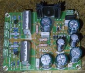
The version of the BOZ I have has a PSU onboard and just needs a single 18v AC rail.
It is labelled 'Pass JFET BOZ' near the centre and at the bottom corner 'by XR0001 2013 01 24 v1.1'
I have never used SPICE although I did install LTSpice a while back.
I'm leaning towards getting some TO-247 MOSFETs instead of using some of the TO-220 ones I already have, is the venerable IRF240 still the best choice or is there something else that would be better? I understand they must be enhancement mode type rather than depletion mode. I was just wondering if a more modern MOSFET might be preferable?
Interesting, I'm not familiar with that version of the BOZ. In that case, it would be possible for the preamp to share a power supply with the power amp. Probably wise to put an RC filter between the two to drop the voltage going to the preamp.
The IRFP240 is still the way to go for the power MOSFET. It has been updated with a lead-free package. There is no need for special matching between the pair used in a channel, or between channels for that matter. The bias adjustment will take care of the variation in Vgs. As long as the two channels are biased within 0.1 Volt of each other, they will be fine.
The Illustrated Build Guide for the newer version of the boards (v1.6) will have a lot of good tips for mounting the MOSFETs to the heatsink and adjusting the bias. Note that the heatsinks used for the current boards are 80mm X 200mm, with 30mm deep fins.
I recommend getting a Mean Well SMPS brick: GST120A24-P1M. One of these has enough current (5A) to supply both channels, and is an easier and less expensive way to go than building your own linear power supply. I am still using these with my monoblock ACAs. Not all SMPS supplies are created equal, but this one is more equal than others.
Thanks for all the advice, it's very much appreciated.
I've decided on what to do - build an integrated with a headphone jack so it can do double duty.
Chassis is an old Sharp SM-1144 chip amp from 1983 that I have stripped down and will reuse the front panel and it's switches and pots.
I have some bigger toroidals I had put to one side for a planned class A power amp build that I can use for this as I have four identical units made by Linton, a British company. They have four secondary windings giving 13.8v, 30v, 30v and 25v, not sure of the VA but they are 3.2kg in weight and should put out ample current I think, I should be able to squeeze two of them into the chassis and then use the four 30v windings to power the ACAs and one of the 25v windings for the BOZ.
I have two LM317/337 boards to provide the dual rail supplies for the ACAs and two dual rail capacitor arrays I built a while back, so I think I'm covered for the PSUs with the parts I already have to hand.
I decided to go ahead and solder the TO-220 IRFB4019 MOSFETs in place, I already have the necessary nylon washers and silicone pads to mount TO-220 parts. The heatsink will be the one that was in the Sharp amp, it's a nice solid extruded aluminium piece that measures 21cm x 8.5cm x 3.5cm and I think will be adequate for the task. I will simply drill 4 holes in it for either self tapping screws or nuts and bolts.
I'll take some pics of the parts tomorrow.
BTW, what is the best way to implement the headphone output? Will the BOZ drive a set of headphones meaning I can connect the headphone jack to the BOZ output? I have some audio line transformers I could use to drive the headphones.
This sounds like it will be an interesting and adventurous build for you. The old Sharp chassis is a great looking vintage piece of gear. Its single internal heatsink will, however, be hard pressed to dissipate the heat that you will be asking of it.
Lets run some numbers: 30VAC secondary voltage x 1.4 = 42 Volts rectified. There will be a loss of 1 to 2 Volts through the rectifier diodes (chassis mount bridge rectifier recommended), so figure on about 40V after the first big bank of capacitors. Now, 40V x 1 Amp = 40 Watts total per channel that must be dissipated somehow. If you are using an LM317 regulator to produce a 20 Volt power rail for one channel of the ACA, then that part must dissipate 20 Watts. It would need its own large heatsink to do that, and would be at its absolute maximum power and current rating. This is not a good recipe for success.
The two large power toroids that you have would probably be excellent for a large amp such as an F5 Turbo, but are not a good match for a small integrated amp based on the ACA.
Since you have chosen the IRFB4019 MOSFETs, you will need to be aware that they need approximately 20% higher Vgs to turn on. It may be necessary to adjust some of the resistor values on the ACA board to accommodate this. Being designed for Class D amps, they appear to be pretty easy to drive (low total gate charge, low gate capacitance), and have a high transconductance. They may or may not be optimum for linear operation in a Class A design. Your ears may be the judge of this. They will also be running at a higher percentage of their maximum power rating than we like to use for Class A, so their lifetime might be reduced.
I can't offer much advise on how to implement a headphone output, so hopefully others can chime in with that. There are a couple ongoing discussions in other about headphone outputs, to the information is out there.
Wonderful, this is precisely the sort of advice and guidance I need, so I am most appreciative of your time and effort.
I think I can see now that it is a very good idea to properly match up the disparate parts I am going to use to avoid making things any more difficult than necessary, keeping things simple is important for me as I'm still very much a novice at this and I chose this project not because I need a new integrated amp, but because I have a lot to learn about amp construction before I take on my eventual plan of a pair of class A power amps to a design such as the F5 or JLH 1969.
I'm not wedded to using the LM317/337 boards, I just happen to have them in my box of parts, I am happy to use a different solution more suited to the power handling requirements.
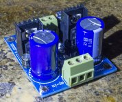
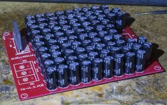
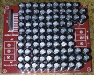
Given I have these two dual rail cap banks that should smooth out the power very nicely with 45x Nippon Chemicon 470uF 50v caps per rail, for a total of 90 per dual board, then the Meanwell SMPS solution might be a good one methinks, the cap banks working well with the Meanwell to produce good, smooth power.
Heatsinking I can work on, I have other heatsink bits lying around, I'll have to have a think about how the physical engineering will work, it will probably entail fitting larger heatsinks externally sticking out the back of the chassis which will give an added advantage of leaving more real estate free inside to fit in all the circuitry neatly.
I'm torn on the MOSFET issue, whether to build it with the IRFB4019s and see how it sounds, or to avoid any possible issues and just get the recommended IRF240s.
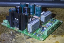
Here's some pics of the parts, I'll take some chassis pics as well shortly.
I think I can see now that it is a very good idea to properly match up the disparate parts I am going to use to avoid making things any more difficult than necessary, keeping things simple is important for me as I'm still very much a novice at this and I chose this project not because I need a new integrated amp, but because I have a lot to learn about amp construction before I take on my eventual plan of a pair of class A power amps to a design such as the F5 or JLH 1969.
I'm not wedded to using the LM317/337 boards, I just happen to have them in my box of parts, I am happy to use a different solution more suited to the power handling requirements.
Given I have these two dual rail cap banks that should smooth out the power very nicely with 45x Nippon Chemicon 470uF 50v caps per rail, for a total of 90 per dual board, then the Meanwell SMPS solution might be a good one methinks, the cap banks working well with the Meanwell to produce good, smooth power.
Heatsinking I can work on, I have other heatsink bits lying around, I'll have to have a think about how the physical engineering will work, it will probably entail fitting larger heatsinks externally sticking out the back of the chassis which will give an added advantage of leaving more real estate free inside to fit in all the circuitry neatly.
I'm torn on the MOSFET issue, whether to build it with the IRFB4019s and see how it sounds, or to avoid any possible issues and just get the recommended IRF240s.
Here's some pics of the parts, I'll take some chassis pics as well shortly.
Attachments
Ian, the BOZ and ACA boards that you have should be Ok as parts of an integrated amp. I would set aside the others for a different amp that uses dual rails. The BOZ and ACA are both single rail designs (+V / Gnd). Once you finish your integrated amp, take some time to read the build guide guide for the F5. You will notice that a dual-rail power supply for a Class A amp looks very different from the boards you have.
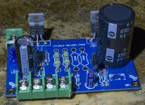
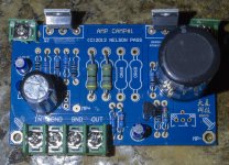
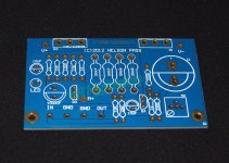
Hmm, I think the ACA boards I have are dual rail, here is a picture of one unpopulated and as you can see, there are V+ and V- connection points either side of the MOSFETs, which I took to mean it was dual rail, but maybe it is single rail and the V- is actually Gnd?
These are Chinese copies of the ACA board, so maybe they made some changes to Nelson's original layout and changed it to dual rail?
If they are single rail, no problemo, I have other parts that can be used to create a suitable single rail supply for each ACA.
These are Chinese copies of the ACA board, so maybe they made some changes to Nelson's original layout and changed it to dual rail?
If they are single rail, no problemo, I have other parts that can be used to create a suitable single rail supply for each ACA.
Attachments
Last edited:
- Status
- This old topic is closed. If you want to reopen this topic, contact a moderator using the "Report Post" button.
- Home
- Amplifiers
- Pass Labs
- Amp Camp #1