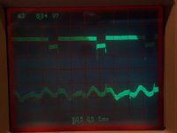
I have a Threshold 400A on the bench. Customer complaint: 60hz buzz in left channel. Sure enough, I hooked it up to the UPL and there's 45mV of 60Hz square wave superimposed on 2MHz RF oscillation in the left channel.
Both channels exhibit the RF at about 2Mhz, but the left has the fast rise
time 60Hz imposed on it that looks like a TTL logic square wave negative pulse train on the 'scope.
I have a hunch this is a transistor issue, but I went ahead an recapped the left channel PCB anyway. My hunch that it wasn't bad caps was confirmed. New caps made no difference.
Seems like a ground loop somewhere within the amplifier, but the wiring suggests a proper star topology. I doubt the problem existed when the amp was new, so I'll assume that a component failure somewhere is causing the issue.
I also measured across the main filter caps. No RF or any sign of 60Hz hash found there.
My next thought is to replace the 680pF mica caps on that driver PCB, thinking that if one channel is oscillating, then at 2MHz, that noise would get into the rest of the circuits.
I also tried testing each channel by removing the rail fuse for the other. If I remove the right rail fuse and power on the amplifier, the left channel noise level is under 0.1mV for about 10 seconds, then the 2MHz RF plus the negative going square pulses with a 60Hz period resume with an amplitude of 45mV. The noise looks like the output of a TTL logic circuit, rather than hum, except that it is line synchronous.
If I pull the left channel rail fuse and replace the right rail fuse, the right channel exhibits some chopped sinewave 60Hz noise and, after a few seconds, will exhibit the 60Hz squarewave pulse train, but at only 10mV.
Visual inspection revealed no evidence of component failures or overheating. As this is a mechanically challenging amplifier to disassemble, I want to head into the problem with as much background information as I can find.
I'm hoping that perhaps Nelson Pass would have some insight as to exactly where this peculiar behavior is originating.
Odd that it's not 120 Hz rep rate.
Double check the 5.1 ohm / .1uF snubbers, then DC voltage across the
300/130/130 ohm CCS emitter resistors and the Collectors of the 6571
diff pair and also the Collectors of the output devices.
After that I would take a 100 pF cap and poke it in parallel with the
<100 pf compensation caps and see what that does.
Thank you for the prompt feedback.
I'll delve into it again tomorrow, when I get this McIntosh unit done that I'm currently working on.
It IS an odd issue, almost like the rectifier is firing on one pair of diodes, but the ripple across the main caps is 120Hz sawtooth, albeit a bit uneven, with alternate peaks slightly taller.
Will check tomorrow and report my findings. Again, thank you for these suggestions!
Just a thought. An oscilllating CCS can cause some strange symptoms and I’ve seen low level oscillations like you describe before. You will usually see a slight difference in the DC Vbe level on the misbehaving CCS compared to the good channel. I haven’t seen a schematic of the 400A but the symptoms sounded familiar.
There are 4 output collector voltages per channel.
What is the voltage at 6571 collectors?
Ah, right.. I forgot that there is a series bank..
The collector voltages on the inner bank are -26.44V and + 26.84V
The 6571 collectors are 7.56V and 7.55V.
I am also wondering about the possibility that one or more components is degraded in a manner that is causing oscillation. You'll notice that the scope trace is thick--that's the 2MHz riding on top of it.
For the heck of it, I tried putting snubber caps around the bridge rectifier. It made the pulse train on the output increase in amplitude by about 50%.
RF makes audio gear do strange things. My hunch is all the problems stem from the oscillation. I'm wondering whether to replace the 6571 and MPSA42 devices. Are the any matching requirements for these parts?
In your situation I would measure the input and output DC offsets then input a signal to see if the amp was still functional and that the LF gain was as designed. If so, it’s unlikely that any transistors are totally shot. In my situation I was able to fix the oscillation by increasing the values of the series base resistors in all the CCS. This was in a diy design, not in an older amp. I then had to verify stability for all reasonable operating conditions.
The output DC offset is under 50mV for both channels.
The amplifier functions normally, has a flat frequency response and seems fine in all other respects, excepting the RF-induced hum. Something common mode is at play here.
I'm quite certain no transistors are failed, but I'm not certain that some haven't degraded or developed some form of leakage current. It's not likely it left the factory like this either. 30mV of square pulses would be quite audible and result in an immediate service call unless the buyer were seriously deaf.
I see there's two 4.7K resistors at the input, in conjunction with a 300pf capacitor, forming a low pass filter. By increasing those resistors, you reduce the bandwidth of the input stage, which may offer more stability.
Mechanically, I'm finding it to be a bear to work on because of inadequate service loop on the wiring. Already had a fuse holder on the right channel break because the wire tugged on it a bit and the metal must have been brittle. Now I need to replace a fuse holder.
Breakthrough Solution--Grounding
I just cut the ground connection from the power supply common to the chassis. All hum, buzz and RF oscillation ceased.
What led me to this path was noticing that when I moved the loosened left heat sink, depending on its connection to the chassis, the pulse train would alternate to the right or left channel. That convinced me it was a ground loop within the amplifier.
I've seen this sort of thing on Hafler 500s and XL600s. It is necessary to change the grounding topology to make them stable under some conditions.
So I have the ground wire disconnected from the chassis ground and the back plate connected to the rest of the chassis and hum and noise dropped well below .5mV in both channels.
I need to replace two fuse holders (the other speaker fuse holder terminal just broke while I was in there unsoldering the ground from the bottom of the chassis and I have had to jumper across both fuse holders temporarily to continue testing), but I think this is a satisfactory solution.
- Status
- This old topic is closed. If you want to reopen this topic, contact a moderator using the "Report Post" button.
- Home
- Amplifiers
- Pass Labs
- Threshold 400A: 60Hz square @45mV pulse train left channel