Yes, the uber important aspect of diy for me is the fun part.
yup
at least for last decade , for me it's 90% , or even more
learning is fun
good luck finding a mate for IRFP150
Maybe look into IRFP140 / 9140? Still single die (I think) but you trade some voltage capacity for some current capacity. Not much more capacitance than 240 / 9240 too.
1. ok
2.5U/500 Modushop , as minimum
3.no worries ; Iq is not changing drive demands
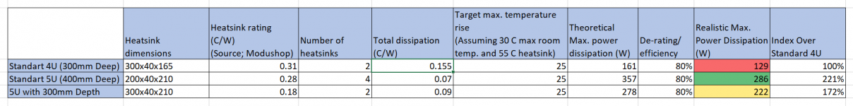
Zen Mod, I was thinking about the chassis, 500mm deep will be a bit on the bigger side, difficult to position it in the room. I ran numbers with 400mm deep (see attached table), it looks like OK;
i) With an efficiency/de-rating of 80% and
ii) Target heat sink temperature of max 55C in a 30C room
Per chassis they can dissipate 286Watts, which is very close to 288Watts dissipation need from 24V rails and 1A bias per device.
What do you think?
Attachments
5U/400 is already darn big
from my experience with 4U/400 and I just once made an amp with 5U/400 ...... I believe 140W per side is too optimistic
however , I can't be sure 100% , just because I didn't make any notes
so , when you finish it , let us know")
Cool, thanks! For sure, will do!
Though, I am still in the process of idea stage, thinking what else overkill that I can do
Obviously, power supply is the usual suspect! My F5 has 8 x 47000 uF capacitors, if I don't exceed that with a good margin, that is a failure on my side!
I was interested not just in current but also in xconductance
Please explain. looks like the 140 Gfs at 11 is somewhere in between the 6.9 of the 240 and 13 of the 150.
Are you worried about the 'curve'? i only ask because I don't know what I'm talking about

Transconductance of IRF mosfets (square law device) is proportional to square root of drain current.Please explain. looks like the 140 Gfs at 11 is somewhere in between the 6.9 of the 240 and 13 of the 150...
I usually estimate transconductance at intended bias by :
Code:
gfs(Id1) ~ gfs(Id2) * sqrt(Id1/Id2)

where :
gfs(Id1)  transconductance at intended drain current
Id1       intended drain current
gfs(Id2)  datasheet transconductance at cited drain current
Id2       datasheet cited drain current
Code:
             Datasheet           Estimate
           gfs   @Id(A)   gfs @1.3A   gfs @2A
N-ch
IRFP140    9.8    19        2.56       3.18
IRFP150   13      25        2.96       3.67
IRFP240    6.9    12        2.27       2.82
IRFP244    6.7     9        2.54       3.15
P-ch
IRFP9140   6.2    13        1.96       2.43
IRFP9240 4.2 7.2 1.78 2.21Regarding the 5U case dissipation, I had one with an F4 running 30V rails and about 0.6A per mosfet. So I had about 108W per side being dissipated. temperature was a nice 45º on the sinks with about 25 room air temperature.
Thanks a lot MASantos!
Have you also tried a bit higher bias?
With 30V rails, moving from 0.6A to 0.8A bias (33% increase) would end up having 144W dissipation per side (as opposed to current 108W)
With that 33% increase, 20 degrees C temperature difference in heatsinks over ambient would increase to 20X1.33 = 26-27 degrees C; which with a 25 C room temperature, ends up being 51-52 C heatsinks.
I wonder whether you have tried and it did not work out or you haven't tried at all.
Transconductance of IRF mosfets (square law device) is proportional to square root of drain current.
I usually estimate transconductance at intended bias by :
Estimating from Vishay datasheets :Code:gfs(Id1) ~ gfs(Id2) * sqrt(Id1/Id2) where : gfs(Id1) transconductance at intended drain current Id1 intended drain current gfs(Id2) datasheet transconductance at cited drain current Id2 datasheet cited drain current
Please note that the estimate is based on Vishay minimum gfs value, no description of typical value. Spread of value is pretty wide, a maximum gfs device can have double the transconductance of a minimum gfs device.Code:Datasheet Estimate gfs @Id(A) gfs @1.3A gfs @2A N-ch IRFP140 9.8 19 2.56 3.18 IRFP150 13 25 2.96 3.67 IRFP240 6.9 12 2.27 2.82 IRFP244 6.7 9 2.54 3.15 P-ch IRFP9140 6.2 13 1.96 2.43 IRFP9240 4.2 7.2 1.78 2.21
Would this mean IRFP 9140 is actually a better match for IRFP 240 (compared to IRFP 9240 that is commonly used)
Disclaimer = I am not really deep in this topic at all, the notion of transconductance is beyond my paygrade
Minor enough difference for me to put on the side, spread of variation is wider. You need curve tracer plot for a good match.Would this mean IRFP 9140 is actually a better match for IRFP 240 ...
Power supply options
First, thanks for the help so far guys. I decided to go ahead with Irfp 240 + 9240 bundles; realising that I already have matched packs from the store (that I purchased a while ago..)
As mentioned before, I have been thinking about the PSU options; as a starting point I checked the PSU of my previous builds;
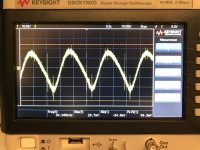
1) My F5 has a ripple of 39 mV (see the screen shot); It has Antek 4218 (400 VA, 2 x 18 V secondaries), Vishal 35A square bridge rectifiers and 8 x 47000 uF capacitance in CRC setup (R = 0.12 Ohm inline with NP’s paper)
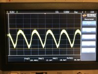
2) I also checked my ACA, it has a remarkable 59 mV after warm up (screen shot attached); It has the Stock 24 Volt 120 Watt Meanwell switching PSU. There is a capacitor in the amp side which acts like a coupling cap, yet I found this result quite remarkable as it is close to my F5.
Another difference is the fundamental freq. of the switching power supply is in 34 kHz as opposed to linear supply which is 100 Hz (in this side of the pond..)
So, I am wondering, what would be the best way forward. Couple of questions that I would love to hear perspectives;
I) Does anyone have a view on the PSRR of balanced F4, I would expect it to be very solid as i) its push-pull principle, ii) balanced operation and iii) low gain ( as such lower risk of amplifying the mains hum), but appreciate any pointers on the topic?
II) How good the 39 mV ripple in my F5 is? Any other benchmarks you can share?
III) Switching mode power supplies, would there be a use case for it. I have seen the power supply of a Soulution 711 in their official website. It looks like they combined bunch of Meanwell PSUs coupled with some very big caps.
Link;
soulution 711 stereo amplifier
Given great results with ACA power supply, I wonder if anyone went this route?
Thanks!
First, thanks for the help so far guys. I decided to go ahead with Irfp 240 + 9240 bundles; realising that I already have matched packs from the store
(that I purchased a while ago..)As mentioned before, I have been thinking about the PSU options; as a starting point I checked the PSU of my previous builds;
1) My F5 has a ripple of 39 mV (see the screen shot); It has Antek 4218 (400 VA, 2 x 18 V secondaries), Vishal 35A square bridge rectifiers and 8 x 47000 uF capacitance in CRC setup (R = 0.12 Ohm inline with NP’s paper)
2) I also checked my ACA, it has a remarkable 59 mV after warm up (screen shot attached); It has the Stock 24 Volt 120 Watt Meanwell switching PSU. There is a capacitor in the amp side which acts like a coupling cap, yet I found this result quite remarkable as it is close to my F5.
Another difference is the fundamental freq. of the switching power supply is in 34 kHz as opposed to linear supply which is 100 Hz (in this side of the pond..)
So, I am wondering, what would be the best way forward. Couple of questions that I would love to hear perspectives;
I) Does anyone have a view on the PSRR of balanced F4, I would expect it to be very solid as i) its push-pull principle, ii) balanced operation and iii) low gain ( as such lower risk of amplifying the mains hum), but appreciate any pointers on the topic?
II) How good the 39 mV ripple in my F5 is? Any other benchmarks you can share?
III) Switching mode power supplies, would there be a use case for it. I have seen the power supply of a Soulution 711 in their official website. It looks like they combined bunch of Meanwell PSUs coupled with some very big caps.
Link;
soulution 711 stereo amplifier
Given great results with ACA power supply, I wonder if anyone went this route?
Thanks!
Attachments
Last edited:
My sims (which are just that: sims) show the FirstWatt production PSU (as used in F4, F5, etc.) at about 160mV. The notable exception is the F3 with about 6mV due to its c-multiplier.
Thanks! I believe this is broadly inline with my measurements. Stock First Watt F5 psu has 8x15000 uF capacitors whereas psu for my F5 build has 8x47000 uF: a bit more than 3x of the stock version.
Hence, ripple going proporationally down (given constant class a bias) would make sense.
- Status
- This old topic is closed. If you want to reopen this topic, contact a moderator using the "Report Post" button.
- Home
- Amplifiers
- Pass Labs
- Balanced Monoblock F4s with very high Bias