arcane technical note: I used an on/off switch that is synchronized to the AC mains. This means every turn-on event in every experiment, occured at exactly the same phase angle of the AC mains. Randomly varying phase angle @ turnon has been eliminated as a source of possible uncertainty.
Douglas Self's "Audio Power Amplifier Design" 6th edition reminds us why, on page 631:
It is characteristic of inrush current that its peak value varies widely from one switch-on to the next, as it depends critically on the [phase] of the mains cycle at which the transformer is connected.
So, for those who are thinking about doing some ICL testing, an on/off switch that is synchronized to the AC mains is a critical piece of gear. It lets you make apples-to-apples comparisons, because every switch-on occurs at exactly the same phase of the mains cycle.
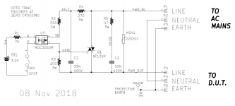
So here is the one I used. Off the shelf test equipment is available which will do exactly what we want, but the gear I managed to find was $uper Expen$ive. Thus I built my own. It's got exposed mains voltages which are very dangerous. So do not copy it. If you DO copy it, against my best advice and disregarding my safety warnings, I disclaim any responsibility for your safety and well being. You do so on your own, I told you not to do this. You have been warned.
Triac Q1 is the power switch that connects AC mains to the Device Under Test, and that disconnects AC mains from the DUT. A specialized optocoupler device called MOC3063M, fires Q1 at the zero crossing, i.e., at phase=Zero of the mains cycle. This happens to be the worst case, giving the highest inrush current, for powering up a transformer. {recall "ELI the ICE man"}
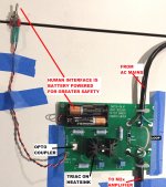
There's a couple of snubbers sprinkled around the triac, for reduced dI/dt and more reliable switching. The input side of the optocoupler, which I nervously touch with my (gloved!) fingertips, is powered from 2 x AA battery cells. For extra safety and isolation from the AC mains.
There is a wire Loop on the board in case I ever want to clamp a clothespin style current probe there. It's a white wire on the right side of the photo.
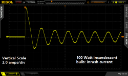
I imagine that Wayne and others may offer suggestions for drastic improvement of this very crude circuit design. However, as shown here, it does actually work. It worked on the first try, no revisions were needed. In fact I attach a scope photo of the very first try, in which I measured the inrush current of a plain ordinary 100 watt incandescent light bulb.
_
Attachments

You may find this Beware of Zero-Crossover Switching of Transformers interesting.... an on/off switch that is synchronized to the AC mains ...
Naah, TE Connectivity merely confirms what EE sophomores already know { "ELI the ICE man" } and what Rod Elliott put on his website years ago. Switching-on a power transformer at zero phase is the worst case, giving MAXIMUM inrush current.
Which is, of course, exactly what I want when measuring inrush current. The worst case maximum. Which is why I chose zero phase switching for my mains sync'd switch.
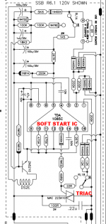
When we stop designing lab bench test gear, and start designing final end-product audio equipment for the home environment, we certainly do not want the worst case maximum inrush current. One way to avoid this is to install ICL devices like SL15-60002, giving a max inrush current of 4 amps instead of 32 amps in the worst case. Another way to avoid it is to install gradual-phase triac drive, as Bryston did in its power amplifiers, years ago. Their Model 2B amplifier (schematics dated Sept 1996) used a motor speed controller chip called TDA1085C, datasheet attached, to implement soft start via gradual-phase triac drive.
_
Which is, of course, exactly what I want when measuring inrush current. The worst case maximum. Which is why I chose zero phase switching for my mains sync'd switch.
A specialized optocoupler device called MOC3063M, fires Q1 at the zero crossing, i.e., at phase=Zero of the mains cycle. This happens to be the worst case, giving the highest inrush current, for powering up a transformer.
When we stop designing lab bench test gear, and start designing final end-product audio equipment for the home environment, we certainly do not want the worst case maximum inrush current. One way to avoid this is to install ICL devices like SL15-60002, giving a max inrush current of 4 amps instead of 32 amps in the worst case. Another way to avoid it is to install gradual-phase triac drive, as Bryston did in its power amplifiers, years ago. Their Model 2B amplifier (schematics dated Sept 1996) used a motor speed controller chip called TDA1085C, datasheet attached, to implement soft start via gradual-phase triac drive.
_
Attachments
For a "typical" clone of a First Watt power supply, such as Figure 1 of post #17 above, there are a total of eight 15,000uF capacitors, charged to about 24 volts. Note that inrush happens long before the optical bias circuit slooooooowly dials up the bias current and begins to tug down upon the rails.
So the total inrush energy is (1/2) * C * Vsquared = 34.5 Joules. And that's the Joule rating we want in our Inrush Current Limiter device.
The First Watt design for 230VAC mains, uses a single ICL device. So it needs the full 34.5 Joule rating. The circuit option for 115VAC mains uses two ICL devices and each one needs half that rating.
This is one reason why I'm happy with the SL15-60002 ICL. It is rated for 50 Joules. Our dear friend the CL-60 is rated for 36 Joules.
Good old DIYers will of course apply the First Dogma Of Homebuilt Audio Gear: "If some is good then more is better". So a big Thank You to Wayne for pointing out the Ametherm MegaSurge line of products: (link). They definitely offer more Joules! Boy howdy.
I'm starting to think that maybe 6L6 is onto something when he says "But a soft start using a great big power resistor with relay bypass, can handle Infinite amounts of inrush Joules, AND it has no voltage "sag" (column 2 in the table of post #17) in normal operation after inrush, thanks to the relay bypass." Hmmm. I say again, Hmmm.
_
So, this SL15-60002 ICL, rated for 50 Joules, could equally be used for 230 Vac ?
So, this SL15-60002 ICL, rated for 50 Joules, could equally be used for 230 Vac ?
If you are using an exact copy of the First Watt power supply circuit, as shown in post #6, including those eight 15,000uF filter capacitors and the transformer with 2 x 18VAC secondary windings,
then, I believe,
Yes; the "240 Volt" option shown at bottom left, can be used with an SL15-60002 ICL in position "TH"
{Click on image to see it full size}
If you are using an exact copy of the First Watt power supply circuit, as shown in post #6, including those eight 15,000uF filter capacitors and the transformer with 2 x 18VAC secondary windings,
then, I believe,
Yes; the "240 Volt" option shown at bottom left, can be used with an SL15-60002 ICL in position "TH"
Oh yes Mark, I am not smart enough to try something else than what is planned.
Can it be also use on TH1 ?
Thanks for your reply.
For my M2X mono blocks I use a type like this to handle the inrush current:
B57364S0100M000 | EPCOS Termistor, 10Ω +-20% Tolerance, 5100mW, For Blod motorstart, switch-mode stromforsyning, 100s, 21 (Dia.) x 7mm | RS Components
It works perfect. I use 500 VA toroid's (single primary, double secondary) with 10 x 35.000 uF capacitors in each mono block I live in a country with 230 - 240 VAC. I use 2A slow fuse in primary. I have been too lazy trying with lower values. I am happy as is. I power-on amp every day and never had a problem with blown fuses. So keep it simple!! ….no need for fancy solutions. For added safety I use rail fuses.
For my M2X mono blocks I use a type like this to handle the inrush current:
B57364S0100M000 | EPCOS Termistor, 10Ω +-20% Tolerance, 5100mW, For Blod motorstart, switch-mode stromforsyning, 100s, 21 (Dia.) x 7mm | RS Components
It works perfect. I use 500 VA toroid's (single primary, double secondary) with 10 x 35.000 uF capacitors in each mono block I live in a country with 230 - 240 VAC. I use 2A slow fuse in primary. I have been too lazy trying with lower values. I am happy as is. I power-on amp every day and never had a problem with blown fuses. So keep it simple!! ….no need for fancy solutions. For added safety I use rail fuses.
What is the voltage drop across B57364S0100M0 when your amp is running? Did you, by any chance, measure its running temperature?
What did you end up using as TH1?
Last edited:
Power Supply Limiters
I am in the process of changing my Aleph J to a dual mono power supply. At 200 watts of current draw each supply will only have a load of 100 watts and each leg of the primary will only see 50 watts. It seems like this will be much too low of a load for a CL-60 to operate properly. How can I come up with a better current limiter match for my situation? Also will the dual supply change the requirements for the power supply ground to chassis limiters. R.B.
I am in the process of changing my Aleph J to a dual mono power supply. At 200 watts of current draw each supply will only have a load of 100 watts and each leg of the primary will only see 50 watts. It seems like this will be much too low of a load for a CL-60 to operate properly. How can I come up with a better current limiter match for my situation? Also will the dual supply change the requirements for the power supply ground to chassis limiters. R.B.
Be prepared to make two or possibly three attempts before you get something you're completely happy with. You'll need insulated gloves, a multimeter that measures AC voltages as high as 200V, and a thermometer to judge how well you're doing. Ideally a no contact infrared thermometer.
For your first try, draw the complete circuit schematic of the power supply all the way from the mains plug to the primary winding(s) of the transformer(s). Draw the Inrush Current Limiters on the schematic and, next to each ICL, write the maximum AC current it will carry.
Then make a list of all ICLs whose "max steady state current" closely match the numbers you wrote on your schematic. This list is your set of Candidates.
Finally, choose whichever ICL on the Candidates list, that has the largest cold state (25C) resistance. Done.
_
Attachments
Earlier in this thread there was discussion of nuisance failure of fuses. This might have been part of the stimulus for investigating switch-on surge limiting. There was also some discussion about choosing a suitable slow-blow fuse rating that would avoid nuisance failures, without any real conclusion. Transformer buzz was mentioned in passing.
With regard to fuse ratings: There is some useful information in a guide from Littelfuse: https://www.littelfuse.com/~/media/...ittelfuse_fuseology_application_guide.pdf.pdf. This talks about the energy needed to blow a fuse (I2t: Amps-squared seconds), equations to estimate this value for various surge envelopes, and derating factors for a number of repetitions of the surge (e.g. 29% for 10,000 surges). Derating for ambient conditions is also mentioned (this can be a significant amount for slow-blow fuses in "warm" applications). A fuse may then be chosen with a suitable current rating and I2t rating. An NTC thermistor can provide a method to alter the I2t surge energy, aiding selection of a fuse that is sensible for the steady-state current that can also handle the surges.
Rod Elliott has discussed the presence of small levels of DC on the AC mains and mitigating it with large-value series capacitors (bypassed with parallel back-to-back diodes for initial switch-on). He related small levels of DC on a transformer primary to high primary currents and increased buzzing.
A little while ago I was looking into a power supply design and I pulled together a number of these threads into a single prototype. It was overkill for the application (a ~50VA E&I lamination transformer), but I later applied the same principles to some preamps with toroidal transformers (with very low current-rating slow-bow fuses and a significant switch-on surge).
I was looking to counter the transformer magnetizing current with an X2 capacitor in parallel with the primary (to improve the power factor and reduce incoming steady state current); add MOV surge suppression (parallel with the primary); add inrush limiting (NTC thermistor), slow-blow fuses in both active and neutral feeds (paranoia in case of incorrect building wiring) and DC-blocking capacitors (with diodes in parallel) all in series with the primary. On the secondary I added snubbers to address diode commutation noise. The MOV is oversized (to handle more energy). I selected an NTC that is operating at the cooler end of its recommended operating range when in steady state (lower ambient temperature and losses, but in an area of operation giving approximately constant-voltage drop irrespective of modest current variations). The fuse is necessary to address the eventual failure of the MOV from an extreme voltage surge or short-circuit failures of the X2 capacitor, in addition to all the traditional transformer failure and overload issues. The capacitor in parallel with the MOV also helps reduce the amplitude of high-frequency surges. The parallel transformer and capacitor mean that one or the other will want to draw a current surge at switch on, no matter if switching is near the voltage zero crossing or the voltage peak. The NTC addresses both. In steady-state operation, the fuses, thermistor and series capacitors together drop a little over 1.5 volts (rms) on the 240V mains supply. I consider this to be acceptable.
A couple quick questions regarding NTC behavior on cold turn-on...
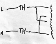
I recently reconfigured my PSU PCB and inadvertently put NTCs (MS22-20005) in both legs of my primary. The amp runs fine, the NTCs do their job, and they run toasty as designed (130-140C). However, on a cold startup I hear two faint hums from the speakers right after hitting the switch.
Questions:
- Is it ok to leave NTCs in both legs of primary?
- If yes, any concern regarding the two faint hums on startup?
rough sketch attached to make clear what my configuration.
Attachments
The preferred method of connecting two ICLs to a transformer whose two primary windings are in parallel (i.e. 115VAC mains), is shown as an attachment to post #6 of this thread.
In post #6, notice that each ICL carries HALF of the total primary current.
Your revision in post #56, has each ICL carrying ALL of the total primary current. The two ICLs are effectively in series.
I myself would tear them out and replace them with two brand new ICLs, fresh from Mouser.com, connected as shown in post #6. It's a small expense and a quick modification, and in return you get lower series resistance in the final steady state ("hot") condition. Which means greater secondary voltage and thus, greater power output.
I've never experienced faint hum on startup myself, so I have nothing helpful to say about that situation.
Any errors?
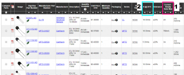
Based on my reading of these here pages, I've found SL22 12103 (datasheet) to be a suitable ICL for:
This ICL is rated at 80 Joules, Max steady state current of 3 amps, 120 ohms resistance, 150C temperature at max current, among other specs.
The thing is, I don't know enough to know if I've erred, or why.
So if anyone could point out any mistakes - and also confirm that I need one, not two - I'd appreciate it.
Cheers!
Based on my reading of these here pages, I've found SL22 12103 (datasheet) to be a suitable ICL for:
- 230V at the mains
- 300VA transformer with dual 22V secondaries
- 2x monolith bridge rectifiers (400V, 35A)
- 2x Juma/Prasi CapMx boards (65.8k uF per board, link)
- F4 Power Amp
This ICL is rated at 80 Joules, Max steady state current of 3 amps, 120 ohms resistance, 150C temperature at max current, among other specs.
The thing is, I don't know enough to know if I've erred, or why.
So if anyone could point out any mistakes - and also confirm that I need one, not two - I'd appreciate it.
Cheers!
Last edited:
120ohm resistance might be too much for an amp to get into nominal specs (nominal bias current), after power-up. Getting an amp to run at its nominal bias current is required to reduce that resistance... I think that is way too high of a room-temp resistance.
CL-60 has correct room-temp resistance of 10ohms, and it will run at the correct resistance when hot (around 0.15ohms with around 200W of dissipation) which ensures its (the CL-60's) heat dissipation long-run is correct to keep it at 0.15ohms, unless you have an enormous capacitor bank and very powerful transformer - which is not the case with FW amplifier clones.
CL-60 is proven to be working correctly many times over. I do not see the need to change it.
The SL22 you want to test will have to be tested in-circuit to see if its 120ohm resistance will drop when you turn the amp on
You need one CL-60 in series with the primary winding.
- Home
- Amplifiers
- Pass Labs
- Not thrilled with CL-60 inrush limiter in USA/160W Class A First Watt designs