The scope screen shots look about right for 400 VA except for the little spikes. Kind of interesting?
Amatherm makes some in the MegaSurge series up to 900 Joules. Without them you can hear wires hitting conduit in big amps. Lots of fun when you short the rails out with a big knife switch for safety testing. The switches don’t much like it.
Amatherm makes some in the MegaSurge series up to 900 Joules. Without them you can hear wires hitting conduit in big amps. Lots of fun when you short the rails out with a big knife switch for safety testing. The switches don’t much like it.
For a "typical" clone of a First Watt power supply, such as Figure 1 of post #17 above, there are a total of eight 15,000uF capacitors, charged to about 24 volts. Note that inrush happens long before the optical bias circuit slooooooowly dials up the bias current and begins to tug down upon the rails.
So the total inrush energy is (1/2) * C * Vsquared = 34.5 Joules. And that's the Joule rating we want in our Inrush Current Limiter device.
The First Watt design for 230VAC mains, uses a single ICL device. So it needs the full 34.5 Joule rating. The circuit option for 115VAC mains uses two ICL devices and each one needs half that rating.
This is one reason why I'm happy with the SL15-60002 ICL. It is rated for 50 Joules. Our dear friend the CL-60 is rated for 36 Joules.
Good old DIYers will of course apply the First Dogma Of Homebuilt Audio Gear: "If some is good then more is better". So a big Thank You to Wayne for pointing out the Ametherm MegaSurge line of products: (link). They definitely offer more Joules! Boy howdy.
I'm starting to think that maybe 6L6 is onto something when he says "But a soft start using a great big power resistor with relay bypass, can handle Infinite amounts of inrush Joules, AND it has no voltage "sag" (column 2 in the table of post #17) in normal operation after inrush, thanks to the relay bypass." Hmmm. I say again, Hmmm.
_
Last edited:
a soft start using a great big power resistor with relay bypass, can handle Infinite amounts of inrush Joules, AND it has no voltage "sag" (column 2 in the table of post #17) in normal operation after inrush, thanks to the relay bypass.
Some older solutions are indeed better in some aspects to newer solutions. One will often find that the newer solution only has been introduced because of lower price. The use of a non linear part in audio electronics is also so-so
")
Their lives will be significantly shorter if they run hot all the time. And if your amp is really SE class A (essentially constant power consumption from the supply) then as long as it's biasing up and voltage is holding you should be good. Inrush limiters ideally are only there on startup, then try to be wires when running (and warm).
This.
Last edited:
string of NTCs , bypassed with relay after some time,is softest and best
soft start with fixed resistor is not universal solution , needing higher level of optimization (for particular load) than using NTCs in same position
repeating that for years , call me a Preacher , but lazy one
soft start with fixed resistor is not universal solution , needing higher level of optimization (for particular load) than using NTCs in same position
repeating that for years , call me a Preacher , but lazy one
It's "only" 10A peak after 3 cycles, 50mS. This part of the fuse thermal curve (rarely plotted) is practically vertical; a few 32A-10A blips won't usually blow a 2.5A fuse.
Also, it is a narrow peak. Squinting on thumb, maybe 1/10th of a half-cycle. So the heating effect of a 32A rectifier peak is more like a 10 A current; falling to 3A after the 3rd cycle.
Additional datapoint: if a 2.5A fuse blew on a dozens-mS transient, fuses would protect transistors. As we know
All very good points. However, the 2.5A slow-blow fuse on my M2x did in fact blow. It died on about the 30th powerup. I replaced the fuse, and the replacement died too. After another 30 powerups or so. Anecdotally suggesting that overcurrent damage to fuses might be cumulative over the (finite!) lifetime of the fuse.
Fuses blowing when they shouldn't, is what inspired me to perform the experiments mentioned in post #17.
Dropping the peak inrush down to 4 amps, with the new part# ICL, gives me a comfortable feeling that fuses are now going to survive a long long time. Also reading post #13 in which NP admits that First Watt M2's didn't really use CL-60s, but instead a different ICL with a different part number, makes me think that's why nobody complains about nuisance fuse blows on the original M2 amplifiers.
_
Anecdotally suggesting that overcurrent damage to fuses might be cumulative over the (finite!) lifetime of the fuse.
This is not anecdotally but a fact.
We kind of generically show CL60's in everything but use different ones depending on the amp. XS 300 amps have 16 -25K uF caps at 90 Volts so they use triacs big thermistors and relays. I have seen resistors open on some amps open if a relay fails (not ours) an advantage thermistors can have.
Marks chosen one looks great I would trust his work.
Marks chosen one looks great I would trust his work.
We kind of generically show CL60's in everything but use different ones depending on the amp.
You don't mean that the schematic says CL-60 but in reality another type is used do you?
Thank you for the kind words, Wayne! 
On a different thread here in diyAudio, a repair technician mentioned that big Krell amplifiers use a hefty resistor and a relay for soft start. BUT, connected in series with the resistor is a thermal fuse / thermal cutoff like these.
The thermal fuse is mounted physically adjacent to the hefty soft start resistor. If the relay contacts fail open-circuit, so that the resistor is always connected in the primary circuit and never bypassed, the resistor gets super hot. This melts the thermal fuse and the amp stops getting AC mains power. Then a repair technician replaces the relay and the thermal fuse.
BTW these types of thermal fuses are installed inside surge protector power strips. When a gigantic big mama surge comes along and is clamped by a MOV in the surge protector, the MOV gets very hot. This melts the thermal fuse and forces you to replace the surge protector power strip with a fresh virgin unit that's never clamped a gigantic big mama surge.
I use NTC 8D-20, 8ohms at 25C and have not measured what R is when running but they are too hot to touch for long. I should do a test and measure temp and R. They are well priced though at $8 for a bag of 10 vs $7ea for a CL-60.
https://datasheet.lcsc.com/szlcsc/NTC-Thermistor-5R_C69391.pdf
Quick test using Fluke 101 and SMT hot air gun and IR thermometer.
25C 8.1ohm
85C 3.9ohm
134C 2.1ohm
145C 1.5ohm
182C 0.3ohm
https://datasheet.lcsc.com/szlcsc/NTC-Thermistor-5R_C69391.pdf
Quick test using Fluke 101 and SMT hot air gun and IR thermometer.
25C 8.1ohm
85C 3.9ohm
134C 2.1ohm
145C 1.5ohm
182C 0.3ohm
Last edited:
Their datasheet, attached below, is pretty light on details. It doesn't list a total inrush energy rating in Joules, for example. Fortunately the device itself is big, 20mm diameter, so all else being equal it should withstand greater energy than its smaller brethren.I use NTC 8D-20, 8ohms at 25C
Cold resistance is 8 ohms, which is 20% less than the 10 ohm cold resistance of the Amphenol CL-60. So we might expect it to have about 20% greater inrush current peak value than what you'd get with a CL-60. In my setup with my wiring and my transformer + bridges + caps, CL-60 inrush was 15 amperes (see post #17, Fig 4) so I would expect this setup would have an inrush of about 18 amps using the Shenzhen Ruilongyuan Electric 8D-20. But that's just an extrapolation not a measurement.
Me, personally, I prefer the SL15-60002 with a cold resistance of 60 ohms and a long term steady state current of 2A. Its peak inrush current was only 4 amperes in my setup, and Mouser sells a bag of ten of them for USD 8.09.
BTW I got more repeatable temperature measurements with a type K thermocouple than with an IR thermometer. I think the relatively small size of the disc (less than 1") might be part of the reason why IR readings fluctuated wildly.
_
Attachments
Last edited:
Hi Mark,
Bag of 10 from Mouser for $8 is a bargain*. Thanks for pointing out this device and making the measurements.
*There is the $150 Mouser rule. Because a bargain is a relative term when it comes to ordering from Mouser - as I always try to order everything I need that is low supply wise (typically dozens of IRFPs or big BJTs like TTC5200/TTA1943, or assorted film caps - can never have too many Wima film caps) or in prep for next project so can’t seem to ever get an order to be less than $150 with Mouser.
Last edited:
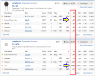
... vs $7ea for a CL-60. ...
Here is what Octopart.com gives me when I ask for today's prices on CL-60 parts:
_
_
Attachments
Mark, thanks for the testing!(snip) Cold resistance is 8 ohms, which is 20% less than the 10 ohm cold resistance of the Amphenol CL-60. So we might expect it to have about 20% greater inrush current peak value than what you'd get with a CL-60. In my setup with my wiring and my transformer + bridges + caps, CL-60 inrush was 15 amperes (see post #17, Fig 4) so I would expect this setup would have an inrush of about 18 amps using the Shenzhen Ruilongyuan Electric 8D-20. But that's just an extrapolation not a measurement.
Me, personally, I prefer the SL15-60002 with a cold resistance of 60 ohms and a long term steady state current of 2A. Its peak inrush current was only 4 amperes in my setup, and Mouser sells a bag of ten of them for USD 8.09.
Did you consider using two CL-60 in series? That would give you ~20 Ohms cold R...
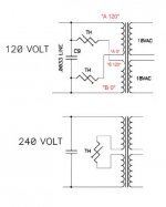
Yes, your idea does represent one valid method to handle the dual mains voltage requirement:
Nelson Pass's First Watt power supply schematic is an unusual and clever implementation of this very idea, in that he has chosen N=1/2 (!) thus 2N=1. He manages to arrange the dual primaries in such a way that each of the two IRC limiters carry half the current, thus they are effectively in parallel, thus effectively (1/2) of an IRC limiter's cold resistance. Schematic attached.
You propose to use N=2 IRC limiters in series for the 115VAC case, allowing you to continue purchasing Amphenol CL-60 parts. This means that 230VAC builders would need 2N=4 components in series. Besides increasing the parts cost, this also increases the voltage dropped across the ICL limiters in steady state, after the inrush. It's now (4 * Iprimary * Rhot) which looks a bit intimidating. Speaking of emotions like intimidation, and individual personal preferences, I mentioned another of mine back in post #6.
_
- For 115VAC mains: connect "N" number of IRC limiters in series
- The inrush peak current is approx [115V / (N * Rcold)]
- For 230VAC mains: connect 2N number of IRC limiters in series
- The inrush peak current is approx [230V / (2N * Rcold)]
- Presto, same inrush peak current in both arrangements
You propose to use N=2 IRC limiters in series for the 115VAC case, allowing you to continue purchasing Amphenol CL-60 parts. This means that 230VAC builders would need 2N=4 components in series. Besides increasing the parts cost, this also increases the voltage dropped across the ICL limiters in steady state, after the inrush. It's now (4 * Iprimary * Rhot) which looks a bit intimidating. Speaking of emotions like intimidation, and individual personal preferences, I mentioned another of mine back in post #6.
_
Attachments
Although I tried numerous ICL devices in my M2x amplifier, I will only mention three of them in this summary
I tested more or less all of the ones I was aware of, and more or less all of the ones which looked promising in Mouser's parametric tables, and more or less all of the ones which seemed to receive the most discussion on pro audio sites and on DIY audio sites.
I only tabulated the three of greatest interest to me, but of course I strongly encourage diyAudio members to experiment for themselves! You will have a lot of fun. Try the ones of greatest interest to you, connected inside a finished piece of audio equipment with a real transformer, real mains switch, real mains fuse, real bridge rectifiers, real filter capacitors, and real internal wiring. You may find that your data is reasonably well fitted by the simple equation
InrushCurrent ==approx== Vmains / (Rcold + XXX)
A quick way to get a first, coarse approximation of XXX, is to short out the ICL(s) with crocodile clip jumpers, then just use a DVM ohmmeter to measure the DC resistance of the entire primary current path. Which is accessible between the Live pin and Neutral pin at the input end of the AC mains cord. Unplugged from the wall of course!
For warm-up and practice, you can try your hand at calculating an approximate value of XXX which gives the best fit (least sum of squared errors), to the tabulated data in post #17 above.
- Home
- Amplifiers
- Pass Labs
- Not thrilled with CL-60 inrush limiter in USA/160W Class A First Watt designs