Pass DIY Addict
Joined 2000
Paid Member
My motivation:
Basically, I wanted to know two things:
1) what are the REAL differences among thermal interface products for mounting mosfets to heat sinks?
2) what are the REAL differences among heatsink finishs/colors/paints in thermal performance for your amp?
Some Background:
Sorting your way though which thermal interface product to use when mounting mosfets to heatsinks for your next amp can be confusing at best, especially if you are new to this arena. There are a variety of products from which to choose - some are easier to find, some are less expensive, and comparing the performance data for each can be confusing. Part of the problem is that thermal performance data is presented in different formats for different products. Some data sheets use the term "thermal impedance" and present data using units of Cin^2/w or Cmm^2/w while others use the term "thermal conductivity" using units W/mK. While related, these are different measures. This is both confusing and makes it rather difficult to conduct an easy or understandable comparison among the available options.
In addition to the differences in the data sheets and the data they present, other variables are relevant including the mounting pressure that holds the mosfet to the heatsink, relative temperatures of the heat sinks, surface area of contact, etc. In short, you need to know quite a bit in order to make any sense of things. I've been reading about this for years and still don't fully understand every single detail that is involved. (yep, go ahead, poke fun at my expense...)
Specific Materials Compared:
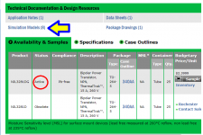
In an effort to help myself and others sort through these differences, I spent some time comparing some readily available thermal interface products: the "traditional" mica wafer & goop approach, various "sil-pad" types of materials including Bergquist K-10, Bergquiest 1500ST, and Keratherm, as well as Aavid 4180G - an Aluminum Oxide Ceramic wafer. Links for each are below and datasheets are attached.
1) "Traditional" Mica insulator (I used the one that was supplied in the VFET2 kit along with some arctic silver compound)
2) Bergquist K-10 (thin brown pad)
3) Bergquist 1500ST (thin blue sticky pad)
4) Keratherm (from DIYAudio store - thin pink pad)
5) Aavid 4180G Aluminum Oxide Ceramic (2mm thick wafer, used with arctic silver compound)
Methods:
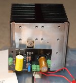
In order to explore the two questions above, I used my MoFo Amp as a test platform because it is a simple amp: there is a single output mosfet that attaches to the heatsink. This makes comparing thermal interfaces while keeping everything else relatively constant just about as easy as it gets. In all cases, the test set up was the same:
a) The MoFo amp started with a cold, room-temperature sink.
b) The bias point was measured and adjusted as necessary to be as consistent as possible from run to run.
c) Rail voltage was measured (and confirmed stable) for each round.
d) Ambient room temperature was recorded before I began each measurement and final temperature measurements were made at exactly 60 minutes with a timer.
e) I made multiple temperature measurements, but the trends were best represented by two measures: 1) placing the thermocouple from my DMM into the divot in the head of the phillips mounting screw and 2) pressing it directly on the top of the sink (without touching the actual probe with my fingers) directly above the mosfet mounting location. I did measure the mosfet body itself in several locations. In each case, the mounting screw demonstrated higher thermal rise and greater consistency of measurement.
f) The same torque was used to mount the mosfet for each interface.
g) I worked in a room where breezes from opening and closing doors would be minimized.
h) The furnace and air conditioning did not run during the time that I was recording my data.
i) Mosfet mounting location was prepped by wet sanding with 300, 400, and 600 grit paper wrapped around an aluminum block to smooth the surface.
While nothing is ever perfect, I tried to make these situations as comparable as possible by only varying the thermal interface material or heat sink finish.
In the first round, I compared five different thermal interface materials with the same amp and same heatsink without changing anything but the thermal interface. The interfaces that used arctic silver compound (mica and aluminum-ceramic) were done last to avoid contaminating subsequent materials.
In the second round, I compared three different finishes for the same heatsink profile: raw aluminum (no coating), the same sink painted brown, and the same sink painted flat black. I don't have the ability or opportunity to have that same sink anodized, so I am unable to make any comparisons here.
Results:
I am sure there is room for criticism here, but the following is what I found:
There weren't any "real" surprises (products that I expected to perform better did) but the magnitude of these differences were somewhat smaller than I had expected.
Which Thermal Interface Performed Best?
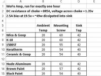
Traditional mica & goop (arctic silver) performed the worst. The mounting screw exhibited a 40c rise. The sink experienced a 22c rise. This was equaled by Bergquist K-10.
Bergquist 1500ST performed notably better (5c lower temp) than the previous two. The mounting screw exhibited a 35c rise, though the final sink temperature was unchanged from the previous two runs and showed a 22c rise.
Keratherm and Aluminum Oxide Ceramic (with arctic silver compound) performed equally well - both exhibiting a 34c rise in the screw head and a 23c rise for the sink itself.
Which Heatsink Finish Performed Best?
Three configurations were compared: nude aluminum, same profile with a flat brown paint, and the same profile again with flat black paint. Again, there weren't really any surprises:
Flat black paint performed the best with the screw head exhibiting a 34c rise and the sink itself exhibiting a 23c rise
Brown was close behind with a 37c rise at the screw head, though the sink itself was only one degree cooler with a 22c rise
The worst performer was nude aluminum with a 41c rise at the screw head and a final sink temp that was the same as brown paint.
Conclusions:
Thermal interfaces DO make a difference. Duh... but now I have data. There was an overall difference of 6c across the various materials. While this is worth paying attention to, the resulting difference in final heat sink temp was smaller than I expected. I suspect if my meter has resolution to the tenth of a degree there would have been greater variations to see. My DMM only reports integer temperatures in Celsius scale.
Heatsink color also makes a difference. Predictably, darker colors radiate heat better. This made a bigger difference for the heat experienced by the mosfet than it did for the final temperature of the heatsink itself. Again, a thermal probe with greater resolution would probably show more detail.
Is it worth the effort to reduce the temperature of your mosfets by 5c or 6c? I think it is. Most data sheets indicate that a 10c reduction in junction temperature typically doubles the life expectancy of the output transistor.
Comments, feedback, and discussion are most welcome!
Basically, I wanted to know two things:
1) what are the REAL differences among thermal interface products for mounting mosfets to heat sinks?
2) what are the REAL differences among heatsink finishs/colors/paints in thermal performance for your amp?
Some Background:
Sorting your way though which thermal interface product to use when mounting mosfets to heatsinks for your next amp can be confusing at best, especially if you are new to this arena. There are a variety of products from which to choose - some are easier to find, some are less expensive, and comparing the performance data for each can be confusing. Part of the problem is that thermal performance data is presented in different formats for different products. Some data sheets use the term "thermal impedance" and present data using units of Cin^2/w or Cmm^2/w while others use the term "thermal conductivity" using units W/mK. While related, these are different measures. This is both confusing and makes it rather difficult to conduct an easy or understandable comparison among the available options.
In addition to the differences in the data sheets and the data they present, other variables are relevant including the mounting pressure that holds the mosfet to the heatsink, relative temperatures of the heat sinks, surface area of contact, etc. In short, you need to know quite a bit in order to make any sense of things. I've been reading about this for years and still don't fully understand every single detail that is involved. (yep, go ahead, poke fun at my expense...)
Specific Materials Compared:
In an effort to help myself and others sort through these differences, I spent some time comparing some readily available thermal interface products: the "traditional" mica wafer & goop approach, various "sil-pad" types of materials including Bergquist K-10, Bergquiest 1500ST, and Keratherm, as well as Aavid 4180G - an Aluminum Oxide Ceramic wafer. Links for each are below and datasheets are attached.
1) "Traditional" Mica insulator (I used the one that was supplied in the VFET2 kit along with some arctic silver compound)
2) Bergquist K-10 (thin brown pad)
3) Bergquist 1500ST (thin blue sticky pad)
4) Keratherm (from DIYAudio store - thin pink pad)
5) Aavid 4180G Aluminum Oxide Ceramic (2mm thick wafer, used with arctic silver compound)
Methods:
In order to explore the two questions above, I used my MoFo Amp as a test platform because it is a simple amp: there is a single output mosfet that attaches to the heatsink. This makes comparing thermal interfaces while keeping everything else relatively constant just about as easy as it gets. In all cases, the test set up was the same:
a) The MoFo amp started with a cold, room-temperature sink.
b) The bias point was measured and adjusted as necessary to be as consistent as possible from run to run.
c) Rail voltage was measured (and confirmed stable) for each round.
d) Ambient room temperature was recorded before I began each measurement and final temperature measurements were made at exactly 60 minutes with a timer.
e) I made multiple temperature measurements, but the trends were best represented by two measures: 1) placing the thermocouple from my DMM into the divot in the head of the phillips mounting screw and 2) pressing it directly on the top of the sink (without touching the actual probe with my fingers) directly above the mosfet mounting location. I did measure the mosfet body itself in several locations. In each case, the mounting screw demonstrated higher thermal rise and greater consistency of measurement.
f) The same torque was used to mount the mosfet for each interface.
g) I worked in a room where breezes from opening and closing doors would be minimized.
h) The furnace and air conditioning did not run during the time that I was recording my data.
i) Mosfet mounting location was prepped by wet sanding with 300, 400, and 600 grit paper wrapped around an aluminum block to smooth the surface.
While nothing is ever perfect, I tried to make these situations as comparable as possible by only varying the thermal interface material or heat sink finish.
In the first round, I compared five different thermal interface materials with the same amp and same heatsink without changing anything but the thermal interface. The interfaces that used arctic silver compound (mica and aluminum-ceramic) were done last to avoid contaminating subsequent materials.
In the second round, I compared three different finishes for the same heatsink profile: raw aluminum (no coating), the same sink painted brown, and the same sink painted flat black. I don't have the ability or opportunity to have that same sink anodized, so I am unable to make any comparisons here.
Results:
I am sure there is room for criticism here, but the following is what I found:
There weren't any "real" surprises (products that I expected to perform better did) but the magnitude of these differences were somewhat smaller than I had expected.
Which Thermal Interface Performed Best?
Traditional mica & goop (arctic silver) performed the worst. The mounting screw exhibited a 40c rise. The sink experienced a 22c rise. This was equaled by Bergquist K-10.
Bergquist 1500ST performed notably better (5c lower temp) than the previous two. The mounting screw exhibited a 35c rise, though the final sink temperature was unchanged from the previous two runs and showed a 22c rise.
Keratherm and Aluminum Oxide Ceramic (with arctic silver compound) performed equally well - both exhibiting a 34c rise in the screw head and a 23c rise for the sink itself.
Which Heatsink Finish Performed Best?
Three configurations were compared: nude aluminum, same profile with a flat brown paint, and the same profile again with flat black paint. Again, there weren't really any surprises:
Flat black paint performed the best with the screw head exhibiting a 34c rise and the sink itself exhibiting a 23c rise
Brown was close behind with a 37c rise at the screw head, though the sink itself was only one degree cooler with a 22c rise
The worst performer was nude aluminum with a 41c rise at the screw head and a final sink temp that was the same as brown paint.
Conclusions:
Thermal interfaces DO make a difference. Duh... but now I have data. There was an overall difference of 6c across the various materials. While this is worth paying attention to, the resulting difference in final heat sink temp was smaller than I expected. I suspect if my meter has resolution to the tenth of a degree there would have been greater variations to see. My DMM only reports integer temperatures in Celsius scale.
Heatsink color also makes a difference. Predictably, darker colors radiate heat better. This made a bigger difference for the heat experienced by the mosfet than it did for the final temperature of the heatsink itself. Again, a thermal probe with greater resolution would probably show more detail.
Is it worth the effort to reduce the temperature of your mosfets by 5c or 6c? I think it is. Most data sheets indicate that a 10c reduction in junction temperature typically doubles the life expectancy of the output transistor.
Comments, feedback, and discussion are most welcome!
Attachments
Last edited:
Pass DIY Addict
Joined 2000
Paid Member
All data is supplied by the manufacturer. Takes the guess work out of it.
I agree- to an extent... The data is always provided, just not in a form that is easily digestible to everyone. Then, there is always the difference between "theoretical" conditions and "real" conditions. Anyone that owns a car knows this about gas mileage.
How much better is Keratherm (at 35 Cmm^2/w) than 1500ST (at 0.23 Cin^2/w)? How much better is thermal conductivity of 6.5 w/mk than 1.8 w/mk? Turns out, not very much at all - about 1 degree C in a real setting. I can get a 10"x12" sheet of 1500ST for $35 - it can be cut into ~150 pads. That's 23 cents each. Keratherm pads are $2 each. Big price difference for a very small performance difference...
I just wanted to make things tangible for people in a real setting.

Pass DIY Addict
Joined 2000
Paid Member
I though I was the only one using ceramic insulators.
I also use and prefer the AlO3 ceramic insulators,
they're indestructible and much less prone to failure then softer insulators that could be cut by the sharp edges of transistors.
How would only thermal grease (the white stuff) compare?
If you did not care about electrical isolation?
MoFo could function this way.
I like housing which is already electrical isolated so only thermal grease is needed but the thermal resistance in the housing is probably larger than metal housing. Can probably be verified from data sheets. So far only "small and medium power" semiconductors uses the electrical isolated housing?
OK, I'll play dumb-dumb.
Why do we care about the temp of the sink? the screw?? Are they going to melt?
The real temp is the Silicon. And since it is inseparable, the device mounting surface.
Yes, it is hard to find a consistent technique to even approximate temp in metal tab or epoxy body. I have seen detailed drilling instructions which may be fine at the factory (screw-up, grab another) but not DIY (order more parts *again*).
An alternate technique is to measure some property of the device. Assuming truly controlled current, a BJT's Vbe is a sweet test. MOSFETs maybe not so simple.
Where is the screw insulation? Is the screw "on" the device or "on" the sink? Or no little washer, so "on both"?
Pass DIY Addict
Joined 2000
Paid Member
MEPER: Thermal grease only is an option I intended to measure, but didn't. I'll have to give it another run and see how it compares. As you point out, this would work only for the MoFo because it uses only a single output device. Don't go trying this with any other amps...
PRR: While imperfect, the temp of the screw is the best proxy for the temp of the mosfet case itself. Sure, a measure of junction temp would be ideal, but this is a little difficult to obtain. The temp of the heatsink is just a curiosity. Since there is often commentary of "use XZY" to mount your devices or, "If your devices are going to run extra hot, then use ABC", I wanted to see just how much of a difference various interface materials actually make. Turns out, the differences between materials seems worthwhile to pay attention to.
PRR: While imperfect, the temp of the screw is the best proxy for the temp of the mosfet case itself. Sure, a measure of junction temp would be ideal, but this is a little difficult to obtain. The temp of the heatsink is just a curiosity. Since there is often commentary of "use XZY" to mount your devices or, "If your devices are going to run extra hot, then use ABC", I wanted to see just how much of a difference various interface materials actually make. Turns out, the differences between materials seems worthwhile to pay attention to.

Did you happen to measure the mosfet body as well? I'm curious if there would be a difference between the screw and the body itself.The screw is embedded in the sink which would wick away heat.The head of the screw is the only part that is in contact with the mosfet itself.
This is really great stuff Eric thank you! I have tried many different options including the exotic graphene interface material from Panasonic but keep coming back to keratherm or the ceramics. Now I understand why.
This would have taken a lot of work to produce and I am very grateful that you did.
This would have taken a lot of work to produce and I am very grateful that you did.
For steady state measurements, Thermal Trak devices provide quite accurate results. Inside the package, there is a diode which is thermally bonded to the same die-attach paddle as the power transistor. The diode is a temperature sensor which quite accurately tells you the temperature of the power transistor's collector. (Since the collector is the die-attach terminal).
Mount it with mica+goop. Shove in X watts. Measure transistor collector temperature.
Rip it off, remount it with Kapton tape. Shove in the exact same number X of watts. Measure temp.
Rip it off, remount it with Beryllium Oxide slab. Shove in X watts. Measure temp.
Rip it off, remount it with Keratherm tape. Shove in X watts. Measure temp.
Rinse and repeat as necessary.
_
Attachments

Last edited:
- Status
- This old topic is closed. If you want to reopen this topic, contact a moderator using the "Report Post" button.
- Home
- Amplifiers
- Pass Labs
- Experiment: Which mosfet thermal interface material is best?