Thank you Mats for sharing your nice build;I did build the Single Ended BA3; 6 deep output stage biased at 4.5 Amps.
2x22.5 Volts. 3x 47 mF per rail, 1200 VA transformer (see pic)
Very stable, sounds great and 55 C on top of fins.
Switchable to run 2x25 W or bridged/balanced 100 W mono block
(using BBA3 FE)
/Mats
Very ingenious approach, it both looks good, is ventilated and practical.
I have some questions:
Is the entire output side biased @4.5 amps or just one side?
How much DC power is this entire build dissipates from your beefy 1200VA transformer? In other words what is the voltage on your source resistors?
Also you used CRC and facing AC you used the weakest capacitor bank. Why this approach?
Thanks Escucalin for comments.
Bias is 4.5 amps on each side (6 deep so 750 mA for each IRFP240, i.e. about 17W each and thus in total about 203 W/side for output transistors.
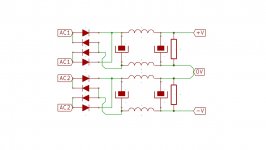
The CRC is (as you correctly noticed) 47 mF --- then 2x0.47 ohms in parallel --- 2x47 mF.
DC power lost in those resistors is another 9*9*0,235*2=38 W
BA-3 F/E is around 5 W.
Grand total 450 W for DC + diode bridge heat + transformer losses so around 500 W draw on the AC inlet (guessing, not measured yet).
The chosen caps (EPCOS Aluminium Electrolytic Capacitor 47000μF 40V dc 51.6mm Screw Terminal B41456 Series, Chassis Mount Electrolytic) have a ripple current capacity of 34 amps and and ESR @100Hz of 6 milliohms.
No real science in the cap configuration, just felt "engineering overkill-good"") with a 3
with a 3
milliohm ESR facing the output stage.
Key takeaway: (has been said so many times in Pass threads but still it is easy to be too optimistic about temperatures) --- everything gets more burning hot than you may anticipate, not only the output transistors, but also the R in CRC, the transformer and the rectifier bridges (guess should be kinda obvious given the BA name).
Bias is 4.5 amps on each side (6 deep so 750 mA for each IRFP240, i.e. about 17W each and thus in total about 203 W/side for output transistors.
The CRC is (as you correctly noticed) 47 mF --- then 2x0.47 ohms in parallel --- 2x47 mF.
DC power lost in those resistors is another 9*9*0,235*2=38 W
BA-3 F/E is around 5 W.
Grand total 450 W for DC + diode bridge heat + transformer losses so around 500 W draw on the AC inlet (guessing, not measured yet).
The chosen caps (EPCOS Aluminium Electrolytic Capacitor 47000μF 40V dc 51.6mm Screw Terminal B41456 Series, Chassis Mount Electrolytic) have a ripple current capacity of 34 amps and and ESR @100Hz of 6 milliohms.
No real science in the cap configuration, just felt "engineering overkill-good"
with a 3 milliohm ESR facing the output stage.
Key takeaway: (has been said so many times in Pass threads but still it is easy to be too optimistic about temperatures) --- everything gets more burning hot than you may anticipate, not only the output transistors, but also the R in CRC, the transformer and the rectifier bridges (guess should be kinda obvious given the BA name
).Thanks Escucalin for comments.
Bias is 4.5 amps on each side (6 deep so 750 mA for each IRFP240, i.e. about 17W each and thus in total about 203 W/side for output transistors.
The CRC is (as you correctly noticed) 47 mF --- then 2x0.47 ohms in parallel --- 2x47 mF.
DC power lost in those resistors is another 9*9*0,235*2=38 W
BA-3 F/E is around 5 W.
Grand total 450 W for DC + diode bridge heat + transformer losses so around 500 W draw on the AC inlet (guessing, not measured yet).
The chosen caps (EPCOS Aluminium Electrolytic Capacitor 47000μF 40V dc 51.6mm Screw Terminal B41456 Series, Chassis Mount Electrolytic) have a ripple current capacity of 34 amps and and ESR @100Hz of 6 milliohms.
No real science in the cap configuration, just felt "engineering overkill-good"
milliohm ESR facing the output stage.
Key takeaway: (has been said so many times in Pass threads but still it is easy to be too optimistic about temperatures) --- everything gets more burning hot than you may anticipate, not only the output transistors, but also the R in CRC, the transformer and the rectifier bridges (guess should be kinda obvious given the BA name
Burning indeed.
But what I do not understand is why you choose to expose the weakest bank to the rectifier? The strongest capacitor (in this case 2x47mF in parallel should face the rectifier) The intention is to have buffered as much instant power as possible for the amplifier?
I can make an educated guess and expect if the ripple resilience for 2 capacitors sums when using them in parallel so you have ~68A for instant consumption, but that's a far cry from what the 0.47R resistors would allow, so the only advantage would be the stored energy it could provide for short required bursts .
I have no clue on how to calculate how much a capacitor bank can provide in order to use the correct capacitance for the amplifier's absolute peak consumption scenarios.
By chance you know how much power this (or) any amp draws in absolute peak conditions? Maybe the sum of all the power the source resistors raised to the rail?
so the absolute max power drawn by this output stage per FET(considering the FET fully open @0.18R) is 22.5V/0.47+0.18R=~35W per transistor, a mind warping instantaneous consumption of 830W that only the capacitor bank can deliver.
I wonder if the capacitor bank can deliver such power for microseconds .
Further more, how to choose the proper parameters for the supply filtering capacitors and resistors(inductors)?
Would be a real waste to have capacitance left completely unused given its cost!
And the R filters that in best case scenario allows 100W of power, a very distant figure from what the amplifier at extreme points needs (i would use CLC an air core inductor of ~1mH and DCR of under 50mOhm also rectifier(s) capable to offer constant current 50A ).
I wonder if such power supply designs details are to be found in a mega Power supply thread for BA3(B) that require such monster power supply.
I haven't find yet or if i'm simply too ignorant to realize that the power supply is already at its best.
The ripple capacity is how much AC a capacitor can handle without overheating. It doesn't (directly) relate to how much current a capacitor can deliver.
A 1200VA transformer should be able to supply 830W directly. And if kept cool, it could do that all day long. Depending on the duty cycle it is rated at, it may or may not keep itself cool if delivering that on a constant basis. But in any case, it could certainly provide that for seconds, not microseconds.
Putting the bank of 4 capacitors first would put a larger load on the transformer. Again, depending on how it's rated that might cause overheating issues or it might not. You'd have to have the specs for the transformer and model it in SPICE or PSUD.
Remember that capacitance provides both storage and ripple reduction. (The two are really one and the same, but never mind that for now.) Depending on the PSRR of your amp you may want more capacitance purely for ripple reduction rather than for peak power demands.
There's a gentleman on these boards with the signature line "Everything matters". That does indeed appear to be the case.
Is clear what is the riple rating and why we should not boil the electrolytic in the capacitor; but scale the supply to what intensity?
Because as far as i see the amplifier will not allow often more than the maximum power rating of the resistors in the filters to pass safely without burning out.
So isn't the safest and cheapest approach to scale all the components in the chain to the weakest link (in this case the R filter)?
I recall in the Ba3 supply the R filter is 5 0.47R @ 3W in paralel on each +/- rail(thats a ridiculous 30W allowed)
I wonder then how is that those resistors at bias current (~10A for a 25V rail = 250W) do not burn out? They are used at more than 10 times the rating at idle.
What am i missing ?
...I recall in the Ba3 supply the R filter is 5 0.47R @ 3W in paralel on each +/- rail...
...bias current ~10A...
What am i missing ?...
5 x 0.47 x (10x10) = R x I x I = 9.4W
...I recall in the Ba3 supply the R filter is 5 0.47R @ 3W in paralel on each +/- rail...
...bias current ~10A...
What am i missing ?...
Hmmmm, I have another Nelson source "BA1 PS", showing 4 x 1 ohm resistors in parallel = 0,25 ohm, thus I kept my build close to this (0.235 ohms).
Note two rails so 9.4 W mentioned above is in total 18.8 W.
From a hum perspective I did measure (using ARTA) the 100 Hz (Europe) frequency component to -80 dB @1W, thus I could probably decrease R for lower dissipation).
I agree that a 1-2 mH inductor would be nice in theory, and did experiment with air core coils -- but they got very bulky already at 0.3 mH (@2 mm2) and also hard to keep them away from the transformer magnetic fields so you get a new set of issues.
The no-compromise solution would definitely be a separate PS-box, containing
transformer, rectifiers and 1st level of caps. The umbilical cord to the amp would be a nicely lukewarm part of the R being discussed, and then optionally an inductor could safely be placed in the amp box (or boxes if mono blocks) together with the 2nd level of caps. Nice thermal distribution and a totally quiet amp for sure.
Given the scary total weight of my amp, it would also be a proactive strategy against back injuries....
Last edited:
...
I recall in the Ba3 supply the R filter is 5 0.47R @ 3W in paralel on each +/- rail(thats a ridiculous 30W allowed)
I wonder then how is that those resistors at bias current (~10A for a 25V rail = 250W) do not burn out? They are used at more than 10 times the rating at idle.
What am i missing ?
I believe what you're missing is that the resistor is only dissipating power proportional to its voltage drop, not the rail voltage. So if you are drawing 10A with a 25V rail, the voltage drop over the resistors is only 1V, so they're handling only 10W, not the 250W of the entire 25V drop.
Cheers,
Jeff.
oh yes ; you are perfectly right the power rating of the resistor is not the actual power that is allowed after it but the power dissipated due to its resistance and is calculated using the voltage drop not the rail voltage doh ; i'm so dumb !!! but i had a feeling i misunderstand something otherwise the resistors in the power supplys would be ... black not brown
... the resistors in the power supplys would be ... black not brown
Oh, I've got a couple of those too.
The ground must have the least resistance so i'm avoiding coiling that way...
It's unimportant, the low impedance point is the 0V junction, the current supplying the speaker(s) (via the output transistors) mostly comes from the last two capacitors, the speaker returns the current to the 0V point completing the AC circuit

Mostly is the key word ; and the reasoning behind my choice is that the return must go all the way to the star point with 0 R if possible.
Any resistance is reverse proportional with the noise rejection capabilities (same principle as the R filter in the power supply, thinking of any resistance on ground as a R filter that as a metaphor keeps the noise in or as a sink ... if is clogged, backflows )
That's how i understand it.
Any resistance is reverse proportional with the noise rejection capabilities (same principle as the R filter in the power supply, thinking of any resistance on ground as a R filter that as a metaphor keeps the noise in or as a sink ... if is clogged, backflows
) That's how i understand it.
Last edited:
...the return must go all the way to the star point with 0 R if possible...
It does, the 0V node is star earth point.
I would agree with keeping 0V as low impedance as possible back to the transformer if a single bridge rectifier is used (the transformer centre tap would be the 0V low impedance point).
However, using a double bridge rectifier changes that situation; the junction between the last two caps now becomes the low impedance point, if you remember your AC theory - have look at the AC current path, not the DC...
I would like to see both possibilities tested.
Considering your option I think that also the physical limitation of a magnetically coupled DC Choke would pose a problem.
The DC ratting of a iron core EI transformer would need to accommodate the absolute maximum DC possible consumption so at least 30A. So would be a mamooth in both size and price :
2 of these custom made to have 5+5 mH@30A DC mode I wonder how much would go
195J30 Hammond Manufacturing | Mouser
Because using such coils rated @5 or 10 A DC ; would be long saturated even at idle
Some colleagues here use these: 159ZL Hammond Manufacturing | Mouser
but as stated above i am wondering: aren't those already saturated by the idle DC ; i mean the first 10 amps? Any load greater than this would render the addition of the coil dead weight, when is most useful.
I wonder how MZM rationalizes the use of such low rated coils.
I've settled on air cores Speakers Intertechnik - Shop - Shop
My BA3(B) single ended is on its way to completion and the inductors I got from the link above fitted just fine under the filtering capacitors posing no threat of saturating or dissipating heat @ 2mm diameter
Thanks for your input guys!
My BA3(B) single ended is on its way to completion and the inductors I got from the link above fitted just fine under the filtering capacitors posing no threat of saturating or dissipating heat @ 2mm diameter
Thanks for your input guys!
- Status
- This old topic is closed. If you want to reopen this topic, contact a moderator using the "Report Post" button.
- Home
- Amplifiers
- Pass Labs
- BA3: Complementary vs. Single Ended