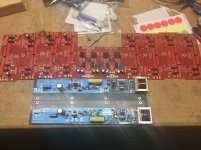
Did a little work this morning. Ideally I get a SissySIT fired up this weekend. I have to do the PSU and boards on #2. And also have a couple F5 V3 turbos in process for a friend.
Attachments
Ah yes, I didnt put in the flying resistors, what is the impact of not including them?
Those are gate resistors and I think they are used to control oscillation but ZM noted they should be as close to the device (SIT) as possible, directly on the pin if you can. Other explanations in the following link:
Does a MOSFET need a gate resistor? | Electronics Forum (Circuits, Projects and Microcontrollers)
But we have tasks at the ice skating rink to get ready for the speedskating race.Did a little work this morning. Ideally I get a SissySIT fired up this weekend..........
+1 more Sissysit alive
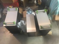
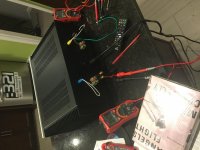
heatsinks @ 55C after 3 hours, no babysitter
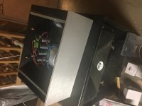
Adjusting offset is tricky - I would set it after and hour or 2 and then it swings through 50+ mV range when I open the cover. I adjust it and come back and it's fine but when I shut off and run next day, it's back to 200mV (+/-). Did this back and forth for 2 days and finally tired of it so connected it to music and speakers today and will monitor it over next few days. Other problem is huge time delay to see Iq and offset change take effect so you must be patient but your patience will be paid back with spookiness!
Thanks to ZM and thanks to Papa!


+ thanks to Jeff Young for sharing the PSU board.
heatsinks @ 55C after 3 hours, no babysitter
Adjusting offset is tricky - I would set it after and hour or 2 and then it swings through 50+ mV range when I open the cover. I adjust it and come back and it's fine but when I shut off and run next day, it's back to 200mV (+/-). Did this back and forth for 2 days and finally tired of it so connected it to music and speakers today and will monitor it over next few days. Other problem is huge time delay to see Iq and offset change take effect so you must be patient but your patience will be paid back with spookiness!
Thanks to ZM and thanks to Papa!
+ thanks to Jeff Young for sharing the PSU board.
Last edited:
Hmm, would it come with too much trouble to convert my M25 to SissySitSIT’s are already awaiting in my drawer.
For once time is not problem, since I’m unemployed very soon.
See Post #1 for both schematics for M25 and Sissysit.
You would be best checking yourself but what I can see:
M25 - D1, D2, D3 (no D4, D5)
Sissysit - remove D1 and D2 and install at D4 and D5
Reverse the direction of install for zeners - ZD1 and ZD2
Remove RS(R and L), P1 goes from 1K to 2K
R19 47K in M25, 36K in Sissysit (R18 stays 43K in both)
R15 270R in M25, 1K in Sissysit
Q3 device changes of course and don't forget the 100R resistor on the gate pin of the SIT.
Looking for help.
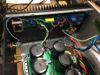
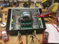
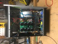
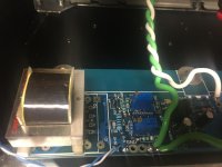
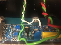
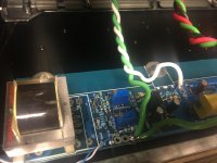
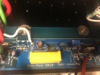
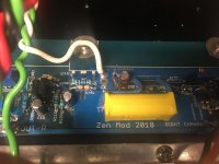
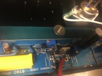
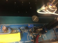
Left channel board is alive and singing. Dead quiet on test speakers. And makes beautiful music.
Right channel board offset is not settling down as nice.
So I thought I would try the driver bias and live with more offset on test speakers.
Set 20mV on R8. Check.
JP to Gnd = 2.7V. Turn increase R7 and voltage goes up. What could be the problem? It is NOT acting like the other channel. Need some insight. Hope the board pix are helpful.
Attachments
-
 1043FE48-80ED-4A40-881D-FCE1B1FE25AD.jpg816.7 KB · Views: 494
 -
 FFA823BD-2F1B-41E6-8A4C-D3C13D53872D.jpg827 KB · Views: 477
 -
 D669E1AD-9924-488F-9044-53617B3A8F01.jpg919.8 KB · Views: 473
 -
 C7E6F576-689D-46C8-B0C0-2C3F35CE9F5B.jpg831.5 KB · Views: 450
 -
 5068501A-198B-4C8A-8FE1-78369E1FB430.jpg834.1 KB · Views: 435
 -
 1983AF2C-A020-47B7-BEA5-2B504FCF0834.jpg879.9 KB · Views: 138
 -
 53BCFC79-6B32-4A83-99A8-ACE222F9C9BC.jpg831.9 KB · Views: 142
 -
 D81B4148-3099-4627-8730-A645D1148DE7.jpg783.6 KB · Views: 150
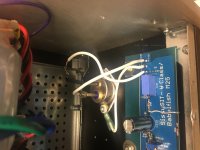
be sure that you're measuring on proper pin of JP , vs. GND
one pin is looking at xformer , another one to buffer output
I'm damn sleepy right now, we arrived at SR less than 2 hours ago , so I'll post nice pic with marked pins for setting buffer DC offset , for both channels
good night ......")
btw. your soldering could be better
one pin is looking at xformer , another one to buffer output
I'm damn sleepy right now, we arrived at SR less than 2 hours ago , so I'll post nice pic with marked pins for setting buffer DC offset , for both channels
good night ......
btw. your soldering could be better
See Post #1 for both schematics for M25 and Sissysit.
You would be best checking yourself but what I can see:
M25 - D1, D2, D3 (no D4, D5)
Sissysit - remove D1 and D2 and install at D4 and D5
Reverse the direction of install for zeners - ZD1 and ZD2
Remove RS(R and L), P1 goes from 1K to 2K
R19 47K in M25, 36K in Sissysit (R18 stays 43K in both)
R15 270R in M25, 1K in Sissysit
Q3 device changes of course and don't forget the 100R resistor on the gate pin of the SIT.
Thanks, nicely summed up
gotta double check, but I’m usually quite blind when modifying circuit.Looking for help.
Left channel board is alive and singing. Dead quiet on test speakers. And makes beautiful music.
Right channel board offset is not settling down as nice.
So I thought I would try the driver bias and live with more offset on test speakers.
Set 20mV on R8. Check.
JP to Gnd = 2.7V. Turn increase R7 and voltage goes up. What could be the problem? It is NOT acting like the other channel. Need some insight. Hope the board pix are helpful.
As ZM pointed out, you've got quite a few open through-holes in the soldering. My first build was an F4 and I didn't get the solder to flow fully through the holes, it created a lot of unstable oscillation behavior... got things steady walked away for a second and turned around to see smoke. Things calmed down when I re-soldered everything so that the solder went completely through the holes (and was filled on both sides)...
See Post #1 for both schematics for M25 and Sissysit.
You would be best checking yourself but what I can see:
M25 - D1, D2, D3 (no D4, D5)
Sissysit - remove D1 and D2 and install at D4 and D5
Reverse the direction of install for zener - ZD1 ONLY!!!
Remove RS(R and L), P1 goes from 1K to 2K
R19 47K in M25, 36K in Sissysit (R18 stays 43K in both)
R15 270R in M25, 1K in Sissysit
Q3 device changes of course and don't forget the 100R resistor on the gate pin of the SIT.
I made a mistake - ZD2 does not need to be reversed between M25 and Sissysit, only ZD1 is reversed.
Okay, M25 is torn apart now, and hopefully become SissySit.
Any problems if SIT is located quite close to transformer?
Oh, ZM, seems like you had an awesome trip to US
Hmm, seems like I’m only ruining my pcb’s..solder points fall off, but I knew this could happen so maybe I’ll just order another set of PCB’s later from ZM. Trying to use heat as little as possible but I guess that my skills are not good enough.
- Home
- Amplifiers
- Pass Labs
- Babelfish M25, SissySIT - general building tips and tricks