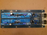
Amp 1 fixed with 2 x 10²R 1% from my stash in R1 and R3 position.
I checked amp kit #2. It seems 2 impostors are hidden in the mix.
Measure all the 100Rs!
Those brown stripes almost seem black when you look at them under a cool white light !!

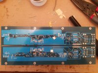
Is it normal to not be able to measure the trimpot settings at r6 and r7? I couldn't, just got .23 ohms, and became convinced I'd ruined them by bending pins. When I pulled them, however, they measured fine (but now are running because I cut them out).
The other two trimpots measure in circuit fine.
The other two trimpots measure in circuit fine.
Both channels. One is on a heat sink, after I tried and failed to start it (over 1v at output and then pulled the plug). Haven't done anything but go to bed on it.
The other isn't installed yet. Also couldn't measure r6/r7 on it. Pulled them and both measured normally, but one was at the wrong value ($!?!$!!). Without any pots installed, both r4/r5 measure appropriately (39 ohms).
The other isn't installed yet. Also couldn't measure r6/r7 on it. Pulled them and both measured normally, but one was at the wrong value ($!?!$!!). Without any pots installed, both r4/r5 measure appropriately (39 ohms).
Thank you all for the tips for tapping. I should have backed them out more often, I think. I did use lube. Tapping jokes never get old... I agree.
ZM, I like the idea to just drill between the fins. Much easier! I'll do that next time.
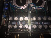
I've made some progress. I thought I'd have the bias process started tonight, but getting the power supplies built and getting the chassis configured took me all day. It's a lot more snug than I thought. I was originally going to mount the donuts vertically, but ... the mounts I ordered are too wide. I may re-visit that later. It's starting to look like an amp.
I got both new PSUs run through the dim-bulb tester separately and then together. +- 26.4V for both unloaded.
Tomorrow, I'll try to get the I/Os and V+ V- to the amp boards, get the CL-60 run to the safety ground, and get it tested and biased. Then I'll clean up all the wiring and button up the chassis.
SISSY MUSIC SOON!
ZM, I like the idea to just drill between the fins. Much easier! I'll do that next time.
I've made some progress. I thought I'd have the bias process started tonight, but getting the power supplies built and getting the chassis configured took me all day. It's a lot more snug than I thought. I was originally going to mount the donuts vertically, but ... the mounts I ordered are too wide. I may re-visit that later. It's starting to look like an amp.
I got both new PSUs run through the dim-bulb tester separately and then together. +- 26.4V for both unloaded.
Tomorrow, I'll try to get the I/Os and V+ V- to the amp boards, get the CL-60 run to the safety ground, and get it tested and biased. Then I'll clean up all the wiring and button up the chassis.
SISSY MUSIC SOON!
Attachments
Is it normal to not be able to measure the trimpot settings at r6 and r7? I couldn't, just got .23 ohms, and became convinced I'd ruined them by bending pins. When I pulled them, however, they measured fine (but now are running because I cut them out).
The other two trimpots measure in circuit fine.
First setting for R7 as per schematic is 0R. 0.23R is pretty close to 0. Not sure if it’s relevant. Mine goes to 0
First setting for R6 is max. So if you got a 100R trimpot in parallel with R4 (39R) you should read something like 28R on the board. 1/39+1/100=1/28

yup ........
naive question - is there really something wrong with boards (both channels !! so veeery small probability for being that) ......... or you didn't set these trimpots in a way it is needed ?
Gremlin , must be , we just need to sort which one ....
Definitely not thinking there's a real problem with the boards, just my stuffing/soldering of them. Couldn't figure out any reason why everyone else could be able to measure the trimpot values in circuit, but I couldn't.
And somehow I did get one trimpot installed incorrectly on the board I didn't try to powerup, so likely that's the case on the other too. Hopefully I didn't destroy anything (no smoke, so that's promising).
Will go over the full schematic & boards today, and ensure everything is in the right place, and maybe then try to install the remaining board.

Thank you all for the tips for tapping. I should have backed them out more often, I think. I did use lube. Tapping jokes never get old... I agree.
ZM, I like the idea to just drill between the fins. Much easier! I'll do that next time.
I've made some progress. I thought I'd have the bias process started tonight, but getting the power supplies built and getting the chassis configured took me all day. It's a lot more snug than I thought. I was originally going to mount the donuts vertically, but ... the mounts I ordered are too wide. I may re-visit that later. It's starting to look like an amp.
I got both new PSUs run through the dim-bulb tester separately and then together. +- 26.4V for both unloaded.
Tomorrow, I'll try to get the I/Os and V+ V- to the amp boards, get the CL-60 run to the safety ground, and get it tested and biased. Then I'll clean up all the wiring and button up the chassis.
SISSY MUSIC SOON!
I just picked up an L-bracket from the local hardware store. You can see some of the hardware in this shot...
(and since you're in the US) It was at Ace if you've got one of those around. The one I got from Home Depot didn't have the mounting holes in a compatible spot for the modshop case.
Attachments
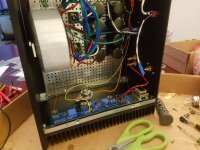
mosfet is somewhat higher than optimal , while SIT would be better suited more to front
If the mosfets were down in the "normal" position (as in the F4 build guide), then there was barely any room for the SIT. It'd be stuck right next to the bottom of the case.
And unfortunately the SIT had to move in towards the middle because that's the only place the pre-tapped holes lined up.
I'm a bit terrified of tapping my own. I'm sure I can learn, but I'd need to pull the amp apart, buy some new supplies to ensure straight holes, and I'm sure there will be failures during the process.
 )
)I just picked up an L-bracket from the local hardware store. You can see some of the hardware in this shot...
(and since you're in the US) It was at Ace if you've got one of those around. The one I got from Home Depot didn't have the mounting holes in a compatible spot for the modshop case.
Thank you very much!
I'll give it a look.Had somehow put a 100k into r1 instead of a 100 replaced that on both boards. Put in new trimpots in the loose board. Double checked every other part on schematic.
And thanks for the tip to measure r4 & r5 (and the math help to look for 28 ohms). I don't know if I had the arrow direction (or pin measurement technique) wrong, but even after pulling and reinstalling the trimpots, I still had them reversed. Now it's clear everything is correct.
Was measuring resistance between pins 2 & 3 and then aligning pin order with arrow direction...
Thanks for all the tech support. About to give powerup another start.
- Home
- Amplifiers
- Pass Labs
- Babelfish M25, SissySIT - general building tips and tricks