naah
rims on mountain bike , ya Dodo .....

For what it's worth, mine are 27 inches.
power it up , .......
wait few mins , calming your breathing
no kidding - I kept waiting for something to release the sacred faerie dust
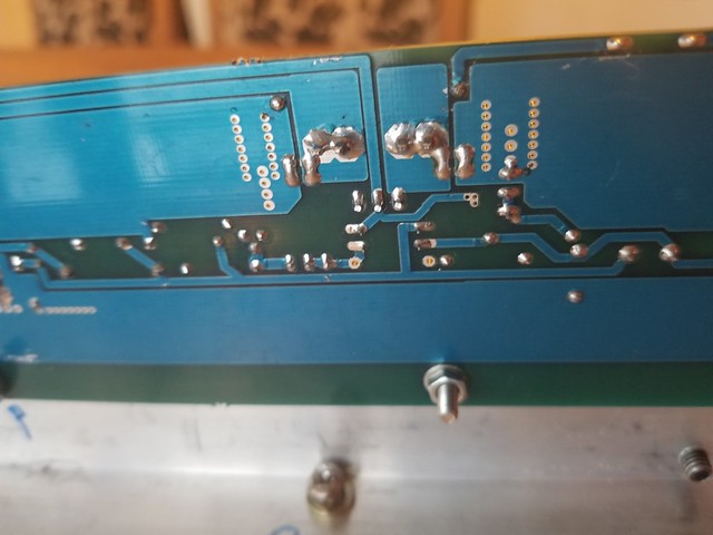
but at least I think I have identified the problem - no 5V to power the HALL effect chips , looks well soldered and the correct orientation, so I will have to explore a little more.
The offset cannot be zeroed but I can get it down to 300mV, the bias settles at 2.6A, the 2K Iq pot has no effect which makes sense given that the opto has no voltage to work with - I measure -0.9V and -.5V at pins 3 and 4.
Both rails at approximately 24 - positive rail looks like it is pulling down a little more than negative rail
I only left it on long enough to do some troubleshooting , very odd that both channels are behaving the same ( although not tested this time - only tested right channel )
..dB
you see what's happening when you are raping pcb with connectors not meant to be mounted here ?
I don't now which of traces you broke , but see - have you positive rail reaching 7805 (most likely you have) , does 7805 is having 5V out .......
in fact , first check is there continuity between 7805 out and Hall, pin 8
I don't now which of traces you broke , but see - have you positive rail reaching 7805 (most likely you have) , does 7805 is having 5V out .......
in fact , first check is there continuity between 7805 out and Hall, pin 8
you see what's happening when you are raping pcb with connectors not meant to be mounted here ?
ouch - no violation intended
they actually work very well but I can appreciate that they are not your preference.
While troubleshooting the right board, I tested the left - it again has no ability to lower Iq but voltage across 0R1 comes up at 150mV with 200mV offset and slowly drifts up to 200mV. I can easily zero offset which remains at +- 1mV and the gate voltage measured at the 100R gate resistor is -4 for the SIT and -4.2 for IRFP9240.
Just giving the right board another piece by piece review and then will assess it. I "think" it might be a poor via contact - lower trace did not appear continuous with upper trace and I had not flooded the solder through the board - now corrected.
..dB
........
While troubleshooting the right board, I tested the left - it again has no ability to lower Iq but voltage across 0R1 comes up at 150mV with 200mV offset and slowly drifts up to 200mV. I can easily zero offset which remains at +- 1mV and the gate voltage measured at the 100R gate resistor is -4 for the SIT and -4.2 for IRFP9240.
......
..dB
so , you're saying that you can set Iq to 2A (but no less) and you can set DC offset ?
obviously you have specific pair of outputs ....... 200mV is on the verge of voltage window for opto-bjt I tested for
so - either looking for mosfet with greater Ugs , or slightly increasing one or both resistors from rails to opto-bjt (R16,R17)
or just leave it on 2A , fine with me
so - either looking for mosfet with greater Ugs , or slightly increasing one or both resistors from rails to opto-bjt (R16,R17)
the right channel now appears to be working too - gate voltages of -3.2 V and the HALL chip is seeing 5V
BUT - still same behavior - starts up at 1.5A and slowly ramps up - this side gets to 2.6A and I cannot s=zero offset completely.
@ZM - how much would you recommend increasing R16/17 ? take them up to 3K2 or even higher?
..dB
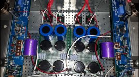
since the Sissy is really an amp that sounds wonderful I decided to refine his qualities. I thought of placing in key points of the circuit where the signal passes some valuable component.
I added the components one at a time to understand how much weight they had in the final result.
then R1 = Vishay z-foil (TX2575), R2 = Caddock MK132, R20 R21 R-flying = Dale RN55.
But the biggest impact on sound was the comparison between capacitors. I was intrigued by ZenMod's suggestion to adopt the old Philips MKC in polycarbonate in parallel to the Silmic II ...... and as I had a pair of 4.7uF Clarity Cap CSA I put them in competition.
having listened carefully to the coupled Silmic + MKC he won tremendously. I invite everyone to try ..... I think nobody will repent.
I am very satisfied at this point .... great sound
Attachments
........ or slightly increasing one or both resistors from rails to opto-bjt (R16,R17)
or just leave it on 2A , fine with me
of course that I made a typo - I meant R18 and R19
I would try to increase them both (if you can center DC offset with standard values) to first standard value
so - 43 to 47K , 36 to 39K
for test , lifting one leg and putting 4K7 in series (to each( will do the job
what are Ugs values of outputs in that other channel?
the coupled Silmic + MKC he won tremendously
Hi Sontero, do you know where to get the MKC´s (what value?) in europe?
best
stefan
hi StefanHi Sontero, do you know where to get the MKC´s (what value?) in europe?
best
stefan
look this from Bulgaria:
2 x NOS 1.0uF 1uF 250V Philips Chicklet MKC 341 HQ Axial Polycarbonate Caps | eBay
so - 43 to 47K , 36 to 39K
for test , lifting one leg and putting 4K7 in series (to each( will do the job
what are Ugs values of outputs in that other channel?
Thanks.
Channel that zeros is about - 4.2V, channel that doesn't are close to - 3.2V
The devices measured on test rig for SIT is about 3.2 and fet is 4.1 at 1.8A
..dB
First impressions with Sissi:
After several problems (I´ve soldered D1+D2 and I didn´t use isolated wires for the bridges which caused a short
fireing up both ACS723 and the opto part - how dump could one be... ) I finished the Sissi test build.
Rails are 23,5V Iq=1,85A Vgs THF51 left channel= -2,2V
Vgs THF51 right channel -2,4V, both IRFP9240 Vgs= -4,6V.
To get the things adjusted well I played a bit with resistor values, ending up in
R18=33k, R19=30k, R15=680R.
Well, how does it sound?
First impression was a muffled and bad structured sound especially on voices.
Hm, that doesn´t match with all previous heard impressions....
I connected the Sissis directly to my CD Player without Iron Pumpi between,
and what can I tell you - that´s a completely different world.
Deep and well structured bass, voices to cry for and an authentic stage in width and depth
And after wiring the Pumpi correct (it´s the balanced version and I forgot
a wire bridge between pin 1+3 on XLR out) it´s playing glorious with Pumpi
between.
Thanks again to ZM you did a great job
After settling the System in two weeks or so I´ll com back with more detailed
findings on sound.
After several problems (I´ve soldered D1+D2 and I didn´t use isolated wires for the bridges which caused a short
fireing up both ACS723 and the opto part - how dump could one be...
) I finished the Sissi test build.Rails are 23,5V Iq=1,85A Vgs THF51 left channel= -2,2V
Vgs THF51 right channel -2,4V, both IRFP9240 Vgs= -4,6V.
To get the things adjusted well I played a bit with resistor values, ending up in
R18=33k, R19=30k, R15=680R.
Well, how does it sound?
First impression was a muffled and bad structured sound especially on voices.
Hm, that doesn´t match with all previous heard impressions
....I connected the Sissis directly to my CD Player without Iron Pumpi between,
and what can I tell you - that´s a completely different world.
Deep and well structured bass, voices to cry for and an authentic stage in width and depth
And after wiring the Pumpi correct (it´s the balanced version and I forgot
a wire bridge between pin 1+3 on XLR out) it´s playing glorious with Pumpi
between.
Thanks again to ZM you did a great job
After settling the System in two weeks or so I´ll com back with more detailed
findings on sound.
I believe he's having them
maybe i got them too, at least the Elna is already bypassed in schematic : )
too lazy to open amp, was it the "blue brick"–cap?
best
st.
Last edited:
.....
too lazy to open amp, was it the "blue brick"–cap?
......
yup
After several problems (I´ve soldered D1+D2 and I didn´t use isolated wires for the bridges which caused a short
fireing up both ACS723 and the opto part -
Rails are 23,5V Iq=1,85A Vgs THF51 left channel= -2,2V
Vgs THF51 right channel -2,4V, both IRFP9240 Vgs= -4,6V.
To get the things adjusted well I played a bit with resistor values, ending up in
R18=33k, R19=30k, R15=680R.
how did you decide that these parts were damaged??
I think this is what has happened as a result of me soldering D1 and D2 too.
With a lot of fiddling, I can zero output on both channels but I have R18 = 33K and R19 = 25K with R15 = 500R
BUT I cannot reduce IqA - I can increase it with P1 but in both channels it starts high and stays high - 2A and 2.6A respectively.
I think I may just order in new opto and ACS723 to try as I do not feel comfortable not having the ability to control Iq
Great to hear that your impressions are as magic as everyone else.
..dB
do not change neither opto nor ACS
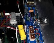
post proper pictures of both channels so I/we can see is there some mistake in parts placement or orientation
in few days I'll start here (or on my blog) proper and full photo-tutorial of SissySIT making , trying to point not just on specific issues with this amp , but also to some general things
however , for your specific case , posting set of proper pictures is best way
- Home
- Amplifiers
- Pass Labs
- Babelfish M25, SissySIT - general building tips and tricks