threads are here :
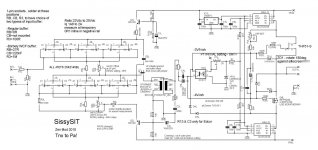
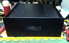
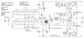
Babelfish M25 , AKA M2 on steroids , AKA M2-XA25 bstrd
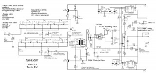
SissySIT
reminder - read everything linked
last , hopefully most clear and informative schematics are here , take care to read all notes !!!!!
Edit on 02.11.2018. :
Populating pcbs :
- as always , mount first all resistors , take care to slightly elevate R8 - to ease measurements across it while setting current through input buffer JFets
-if you're eager to try Borbely White Cathode Follower thingy (input buffer iteration) , read note on left top of schematic ; if you're lazy to do that , just ignore 1-pin sockets you got and normally solder parts , according to mentioned note
-diodes - everything pretty straightforward , except ZD1 - for Babelfish M25 orientate it as silkscreen is showing , for SissySIT orientate it contrary/opposite to silkscreen
take care that Babelfish M25 is having differently connected protection diodes than SissySIT; for B. M25 populate on pcb just those positions shown on B. M25 schematic , for SissySIT populate on pcb just those positions shown on SissySIT schematic !! ...... but you already know that , because you studied both schematics in detail
- two tiny (isolated) wire bridges on right channel pcbs - mount it just for SissySIT , you don't need it for Babelfish M25
-solder trimpots in place , take care of notes in schematic about their initial setting value; it is absolutely essential!!!.... ignore left-right , use ohmmeter to check resistance
-solder all caps , be careful with polarity ..... I tried to ease life for all of us , putting + mark for each position , where it belongs
-solder BD transistors , take care of pinout - metal tab goes where thick stripe on silkscreen is - for both channels metal tabs are looking one at another ; slightly separate them , just to be sure that there is no possibility of contact between them
-solder 7805 regs ; again - metal tab goes where thick stripe is on silkscreen ; don't ask did I made a mistake of mounting at least one backwards
-solder optocouplers ; it's logical looking at silkscreen where corner dot goes ; if it isn't logical to you , see post #593 Babelfish M25, SissySIT - general building tips and tricks
-solder JP pins , leave it open for now , and close it (with that red plasticky thingie) only later when you set buffer DC output offset
-regarding signal xformers ....... as written in previous thread(s) , pcb is made that you can use either Edcor PC600:15K (same one as in M2) , or Jensen JT-123-FLPCH (same one as in M6) , or Cinemag CMOQ-4LPC (same one as in DEFiSIT and SIT-3) .
choose which you want , according to myths and legends , and expect to follow this procedure for Cinemags - locate pin 1 per datasheet , mark it with red dot , then cut pins 1 , 6 , 7 and 12 .......... (no fuss - they're unconnected anyway) ..... that solution was absolutely essential , to be able to squeeze pads for all 3 types .... then find proper orientation on pcb and solder them on pcbs
if you are not using Edcor , and you didn't read notes on schm and you already soldered R13 , just cut it's pins
some pics of necessary xformers trickery , post #62 , Babelfish M25, SissySIT - general building tips and tricks
More about xformer trickery - Cinemag pinout and orientation on pcb , post #652 , Babelfish M25, SissySIT - general building tips and tricks
Edit on 05.11.2018. :
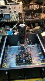
-prepare mosfet(s) , bending their pins up ; in case of Babelfish M25 - because they're practically covered with pcb so you can't see type , it's impossible to see later did you put proper one in position , so maybe is clever to use white permanent marker and write "240" and "9140" on narrow top surface of mosfet case , so later you can check are they properly mounted ; again - don't ask did I tried functionality of Babelfish M25 with two IRFP240 , instead of 240+9140
-it's clever to use Keratherm - bought either from Store , or from conrad.de , for Greedy Boyz being on my side of Big Splash
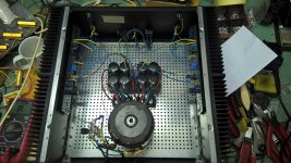
-put mosfets on/under the pcb , in exact arrangement with mounting hardware as can be seen in posts #2 and #3 , just bellow this one ; to remind you , exact arrangement is :
heatsink-Keratherm-mosfet-pcb-big washer-smaller washer if needed-springie washer as absolutely necessary part-bolt
tighten with brain , not force , but not skimp on necessary force ; my solution is to always use stainless steel washers and especially Allen bolt , because nowadays that's only way to have certainly mechanically proper part ........ usual steel bolts are more often utter drek than not
-pcbs are made for UMS , so in case of Babelfish M25 - again see pictures - you have 3 mounting points - 2 are mosfet places , third one single bolt with plastic or metal distancer between pcb and heatsink, long as mosfet thickness ; in case of SissySIT - you have one mosfet place and 2 distancers ; that way pcb is dead spot on
-speaking of SissySIT , there you need some work regarding SIT mounting , but pretty much everything you can see from pictures in SissySIT thread , post #2 especially , but there are others ; SissySIT ; if you have doubt , ask here in thread ; better to use M4 hardware than M3 , but M3 is also OK if you strictly use SS and take care about proper support of isolating bushings etc.
mount both pcbs , and when you bolted everything as needed , then solder mosfet(s) and SIT (in case of Sissy)
Edit on 11.11.2018. :
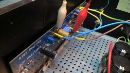
now ...... few words about PSU ...... Papa's mono PSU drawing from F6 article is handy , few more words about - read in post #113 of this thread : Babelfish M25, SissySIT - general building tips and tricks
so , say that you populated pcbs , and mounted everything in case , along with PSU ; for SissySIT - be creative with SIT mounting - take care of proper isolation of everything and proper pinout (body drain , fat pin source , thin pin gate ) and having "flying'' gate resistor as close is possible to gate itself ; heatshrink flying one together with wire , it's stronger critter that way
you didn't forget to test PSU alone ?
best to work on one channel at a time only ; if you have dual mono (which this amp more than deserves) construction , mount mains fuse in one channel only and work on it (you can work on other one , but that's hard to do anything with dead one ) ; if you have (God Forbid!) shared PSU , then wire just one channel to PSU
IMPORTANT: insert 0R1, 3W minimum , resistor in-line with negative rail ; check one more time that all trimpots are where need to be ( read notes on schmtcs) and that JP1 is open ; if you have CRC PSU filter , you can use R in CRC instead mentioned 0R1 in neg. rail ; in that case ,when you set Iq and DC offset , you're done ; don't be alarmed seeing normal surge across that resistor while caps are pulling their juice during power up
mount one DVM across outputs , 2V range ; second one across 0R1 resistor , 200mV range
input shorted , no load on output
power it up , observe output - no more than 1V or so allowed ..... if more , something is fishy - power it off and cry here ; in same time - DVM across 0R1 must stay pretty much undecided ..... few mV or so are allowed
wait few mins , calming your breathing , then turn Iq trimpot 2 or 3 turns .......... wait few mins again to see is there any positive change in readout ; any change will be slow due to enormous RC constant of biasing circuit
turn 2 more turns and observe ........ wait 2 mins and repeat - in one moment there will be change - readout increasing as 3m3 Pana cap is getting juice , which means that gates of SIT and mosfet are going one from another , thus opening both of them for current
be patient - repeat procedure of 1-2 turns more untill you get steady 100 to 120mV across 0R1 , and in same time you can play a little with DC offset trimpot , to get it closer to 0mV
let it sit for some time , to allow heat in heatsink , then fiddle with pot to get more juice in , closer to (say) prescribed 180mV , which means 1A8 flowing through OS
if you're in ballpark of - say- 150-160mV and nice offset , put lid on and wait 10min , observing readouts all the time
coffee or tea are nice to have in proximity , and use it ........
if after 10 min everything is steady , pull lid off , power off and connect other channel ... repeating entire procedure
when you have both channels at 150-160mV across 0R1 , then you can play iteratively between them , to obtain 180mV at monitoring resistor (0R1) and 0mV at output
final fiddle with lid on , of course
when everything is steady , there must be also temp equilibrium of entire case ....... power off , remove both 0R1 and solder negative rail wires in their proper places
power up , re-set output offset , let it cook , re-check offset ;
now is proper time to set input buffers - pretty straightforward procedure , read notes in schematic ; it takes just a little time
in short - put your voltmeter (DC , 200mV range ) across R8 ; fiddle with R6 trimpot to get reading of 20mV , which means buffer Iq is 20mA
connect voltmeter (DC , 200mV range ) between GND and pin1 of JP ; fiddle with R7 to get as close to 0mV you can ; pin 1 is , well - forget orientation - this is one of two pins - showing a change in readout when you fiddle with R7")
when you're done with that , close JP
put lid on , put screws in place
connect cheap dumbass speakers on outputs and your Ipod/pad/phone/CD/playstation/whatever on inputs , put some musak
if cheap dumbass spks are happy , and I'm good for that - connect your precious spks and sources and enjoy
did I forgot something ?
let me know .......
aha - always test isolation between output parts and heatsink ; proper torque is your friend ; use stainless steel screw/bolts/nuts/washers ; always use springie washers , also for Graetz bridges - they are going to die if nut goes loose and they're flapping on bottom of case ; speak friendly with your neighbors .... that way you'll enjoy your music in any time of day or night ; coffee and tea are ...... good outside of an amp ;
edit on 29.11.2018.
R4 and R5 - values changed from 27R to 39R , to cover broader range of input critters Idss ; will edit schmtcs later and bug Mods to change them in this post
edit on 20.12.2018.
I decided to change value of R3 , when used as Borbely WCF - instead of 1Meg , it is now 220K - calmer transient behavior during powering ON
edit on 13.09.2019.
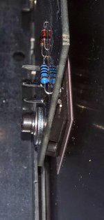
SIT :
body is Drain
big pin is Source
small pin is Gate
Mosfet is , name to your face , pins down - from left to right - G, D, S
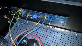
SissySIT parts placement, post #1048
I'll have more if needed, but for now - 42
edit on 17.09.2019. :
P1 pre-set help post #1092 , Babelfish M25, SissySIT - general building tips and tricks
edit on 01.10.2020.
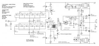
Last iteratioon of schematic , with change to 6N139 optocoupler :
schematic post #1492
pcb sshot post #1529
edit on 31.12.2020. (damned year!) :
ERROR on SissySIT R2 pcb, left channel - post #1820, link : Babelfish M25, SissySIT - general building tips and tricks
ERROR No2. on SissySIT R2 pcb, both channels - post #1867, link: Babelfish M25, SissySIT - general building tips and tricks ; I'm pretty sure that's the last one
Remedy shown in post #1886: Babelfish M25, SissySIT - general building tips and tricks
Babelfish M25 , AKA M2 on steroids , AKA M2-XA25 bstrd
SissySIT
reminder - read everything linked
last , hopefully most clear and informative schematics are here , take care to read all notes !!!!!
Edit on 02.11.2018. :
Populating pcbs :
- as always , mount first all resistors , take care to slightly elevate R8 - to ease measurements across it while setting current through input buffer JFets
-if you're eager to try Borbely White Cathode Follower thingy (input buffer iteration) , read note on left top of schematic ; if you're lazy to do that , just ignore 1-pin sockets you got and normally solder parts , according to mentioned note
-diodes - everything pretty straightforward , except ZD1 - for Babelfish M25 orientate it as silkscreen is showing , for SissySIT orientate it contrary/opposite to silkscreen
take care that Babelfish M25 is having differently connected protection diodes than SissySIT; for B. M25 populate on pcb just those positions shown on B. M25 schematic , for SissySIT populate on pcb just those positions shown on SissySIT schematic !! ...... but you already know that , because you studied both schematics in detail
- two tiny (isolated) wire bridges on right channel pcbs - mount it just for SissySIT , you don't need it for Babelfish M25
-solder trimpots in place , take care of notes in schematic about their initial setting value; it is absolutely essential!!!.... ignore left-right , use ohmmeter to check resistance
-solder all caps , be careful with polarity ..... I tried to ease life for all of us , putting + mark for each position , where it belongs
-solder BD transistors , take care of pinout - metal tab goes where thick stripe on silkscreen is - for both channels metal tabs are looking one at another ; slightly separate them , just to be sure that there is no possibility of contact between them
-solder 7805 regs ; again - metal tab goes where thick stripe is on silkscreen ; don't ask did I made a mistake of mounting at least one backwards
-solder optocouplers ; it's logical looking at silkscreen where corner dot goes ; if it isn't logical to you , see post #593 Babelfish M25, SissySIT - general building tips and tricks
-solder JP pins , leave it open for now , and close it (with that red plasticky thingie) only later when you set buffer DC output offset
-regarding signal xformers ....... as written in previous thread(s) , pcb is made that you can use either Edcor PC600:15K (same one as in M2) , or Jensen JT-123-FLPCH (same one as in M6) , or Cinemag CMOQ-4LPC (same one as in DEFiSIT and SIT-3) .
choose which you want , according to myths and legends , and expect to follow this procedure for Cinemags - locate pin 1 per datasheet , mark it with red dot , then cut pins 1 , 6 , 7 and 12 .......... (no fuss - they're unconnected anyway) ..... that solution was absolutely essential , to be able to squeeze pads for all 3 types .... then find proper orientation on pcb and solder them on pcbs
if you are not using Edcor , and you didn't read notes on schm and you already soldered R13 , just cut it's pins
some pics of necessary xformers trickery , post #62 , Babelfish M25, SissySIT - general building tips and tricks
More about xformer trickery - Cinemag pinout and orientation on pcb , post #652 , Babelfish M25, SissySIT - general building tips and tricks
Edit on 05.11.2018. :
-prepare mosfet(s) , bending their pins up ; in case of Babelfish M25 - because they're practically covered with pcb so you can't see type , it's impossible to see later did you put proper one in position , so maybe is clever to use white permanent marker and write "240" and "9140" on narrow top surface of mosfet case , so later you can check are they properly mounted ; again - don't ask did I tried functionality of Babelfish M25 with two IRFP240 , instead of 240+9140
-it's clever to use Keratherm - bought either from Store , or from conrad.de , for Greedy Boyz being on my side of Big Splash
-put mosfets on/under the pcb , in exact arrangement with mounting hardware as can be seen in posts #2 and #3 , just bellow this one ; to remind you , exact arrangement is :
heatsink-Keratherm-mosfet-pcb-big washer-smaller washer if needed-springie washer as absolutely necessary part-bolt
tighten with brain , not force , but not skimp on necessary force ; my solution is to always use stainless steel washers and especially Allen bolt , because nowadays that's only way to have certainly mechanically proper part ........ usual steel bolts are more often utter drek than not
-pcbs are made for UMS , so in case of Babelfish M25 - again see pictures - you have 3 mounting points - 2 are mosfet places , third one single bolt with plastic or metal distancer between pcb and heatsink, long as mosfet thickness ; in case of SissySIT - you have one mosfet place and 2 distancers ; that way pcb is dead spot on
-speaking of SissySIT , there you need some work regarding SIT mounting , but pretty much everything you can see from pictures in SissySIT thread , post #2 especially , but there are others ; SissySIT ; if you have doubt , ask here in thread ; better to use M4 hardware than M3 , but M3 is also OK if you strictly use SS and take care about proper support of isolating bushings etc.
mount both pcbs , and when you bolted everything as needed , then solder mosfet(s) and SIT (in case of Sissy)
Edit on 11.11.2018. :
now ...... few words about PSU ...... Papa's mono PSU drawing from F6 article is handy , few more words about - read in post #113 of this thread : Babelfish M25, SissySIT - general building tips and tricks
so , say that you populated pcbs , and mounted everything in case , along with PSU ; for SissySIT - be creative with SIT mounting - take care of proper isolation of everything and proper pinout (body drain , fat pin source , thin pin gate ) and having "flying'' gate resistor as close is possible to gate itself ; heatshrink flying one together with wire , it's stronger critter that way
you didn't forget to test PSU alone ?
best to work on one channel at a time only ; if you have dual mono (which this amp more than deserves) construction , mount mains fuse in one channel only and work on it (you can work on other one , but that's hard to do anything with dead one
) ; if you have (God Forbid!) shared PSU , then wire just one channel to PSUIMPORTANT: insert 0R1, 3W minimum , resistor in-line with negative rail ; check one more time that all trimpots are where need to be ( read notes on schmtcs) and that JP1 is open ; if you have CRC PSU filter , you can use R in CRC instead mentioned 0R1 in neg. rail ; in that case ,when you set Iq and DC offset , you're done ; don't be alarmed seeing normal surge across that resistor while caps are pulling their juice during power up
mount one DVM across outputs , 2V range ; second one across 0R1 resistor , 200mV range
input shorted , no load on output
power it up , observe output - no more than 1V or so allowed ..... if more , something is fishy - power it off and cry here ; in same time - DVM across 0R1 must stay pretty much undecided ..... few mV or so are allowed
wait few mins , calming your breathing , then turn Iq trimpot 2 or 3 turns .......... wait few mins again to see is there any positive change in readout ; any change will be slow due to enormous RC constant of biasing circuit
turn 2 more turns and observe ........ wait 2 mins and repeat - in one moment there will be change - readout increasing as 3m3 Pana cap is getting juice , which means that gates of SIT and mosfet are going one from another , thus opening both of them for current
be patient - repeat procedure of 1-2 turns more untill you get steady 100 to 120mV across 0R1 , and in same time you can play a little with DC offset trimpot , to get it closer to 0mV
let it sit for some time , to allow heat in heatsink , then fiddle with pot to get more juice in , closer to (say) prescribed 180mV , which means 1A8 flowing through OS
if you're in ballpark of - say- 150-160mV and nice offset , put lid on and wait 10min , observing readouts all the time
coffee or tea are nice to have in proximity , and use it ........
if after 10 min everything is steady , pull lid off , power off and connect other channel ... repeating entire procedure
when you have both channels at 150-160mV across 0R1 , then you can play iteratively between them , to obtain 180mV at monitoring resistor (0R1) and 0mV at output
final fiddle with lid on , of course
when everything is steady , there must be also temp equilibrium of entire case ....... power off , remove both 0R1 and solder negative rail wires in their proper places
power up , re-set output offset , let it cook , re-check offset ;
now is proper time to set input buffers - pretty straightforward procedure , read notes in schematic ; it takes just a little time
in short - put your voltmeter (DC , 200mV range ) across R8 ; fiddle with R6 trimpot to get reading of 20mV , which means buffer Iq is 20mA
connect voltmeter (DC , 200mV range ) between GND and pin1 of JP ; fiddle with R7 to get as close to 0mV you can ; pin 1 is , well - forget orientation - this is one of two pins - showing a change in readout when you fiddle with R7
when you're done with that , close JP
put lid on , put screws in place
connect cheap dumbass speakers on outputs and your Ipod/pad/phone/CD/playstation/whatever on inputs , put some musak
if cheap dumbass spks are happy , and I'm good for that - connect your precious spks and sources and enjoy
did I forgot something ?
let me know .......
aha - always test isolation between output parts and heatsink ; proper torque is your friend ; use stainless steel screw/bolts/nuts/washers ; always use springie washers , also for Graetz bridges - they are going to die if nut goes loose and they're flapping on bottom of case ; speak friendly with your neighbors .... that way you'll enjoy your music in any time of day or night ; coffee and tea are ...... good outside of an amp ;
edit on 29.11.2018.
R4 and R5 - values changed from 27R to 39R , to cover broader range of input critters Idss ; will edit schmtcs later and bug Mods to change them in this post
edit on 20.12.2018.
I decided to change value of R3 , when used as Borbely WCF - instead of 1Meg , it is now 220K - calmer transient behavior during powering ON
edit on 13.09.2019.
SIT :
body is Drain
big pin is Source
small pin is Gate
Mosfet is , name to your face , pins down - from left to right - G, D, S
SissySIT parts placement, post #1048
I'll have more if needed, but for now - 42
edit on 17.09.2019. :
P1 pre-set help post #1092 , Babelfish M25, SissySIT - general building tips and tricks
edit on 01.10.2020.
Last iteratioon of schematic , with change to 6N139 optocoupler :
schematic post #1492
pcb sshot post #1529
edit on 31.12.2020. (damned year!) :
ERROR on SissySIT R2 pcb, left channel - post #1820, link : Babelfish M25, SissySIT - general building tips and tricks
ERROR No2. on SissySIT R2 pcb, both channels - post #1867, link: Babelfish M25, SissySIT - general building tips and tricks ; I'm pretty sure that's the last one
Remedy shown in post #1886: Babelfish M25, SissySIT - general building tips and tricks
Attachments
Last edited:
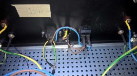
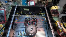
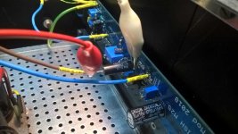
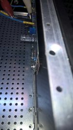
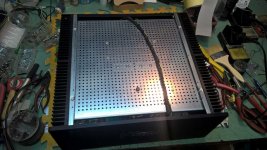
some mute and deaf pics , before going to zzzzzzzz
Babelfish M25 , I used 0 gen pcbs - same set I used on T-Bed for final development of both Babelfish M25 and SissySIT........ later resorted to new ones , made for UMS
Babelfish M25 , I used 0 gen pcbs - same set I used on T-Bed for final development of both Babelfish M25 and SissySIT........ later resorted to new ones , made for UMS
Attachments
-
 WP_20181029_22_40_40_Pro.jpg120.6 KB · Views: 1,145
 -
 WP_20181029_22_41_05_Pro.jpg95 KB · Views: 1,081
 -
 WP_20181029_22_40_59_Pro.jpg78.7 KB · Views: 1,105
 -
 WP_20181029_22_40_14_Pro.jpg59.5 KB · Views: 996
 -
 WP_20181029_21_36_23_Pro.jpg77.8 KB · Views: 981
 -
 WP_20181029_19_25_33_Pro.jpg56.4 KB · Views: 1,159
 -
 WP_20181029_19_25_18_Pro.jpg131.5 KB · Views: 1,221
 -
 WP_20181029_19_24_55_Pro.jpg68.5 KB · Views: 6,945
 -
 WP_20181029_19_24_34_Pro.jpg62.3 KB · Views: 6,969
 -
 WP_20181029_18_29_59_Pro.jpg104.7 KB · Views: 7,298

yeah!
you got me there !!!!
usual ZM's brainfart , editing schmtcs when tired
and I made that mistake more than once ......
will edit tonight
Remove dust from the oscilloscope sometimes.
1st post attachments ammended as requested.
thank you wintermute
Remove dust from the oscilloscope sometimes.
more benefit of keeping tutorial thread clean , then scope
I was looking at the cinemag and am not entirely sure what you mean by cutting the 4 outer pins. I am guessing that it will make more sense when I have the board to make better sense of it.
NVM - I see it now..dB
interesting reading about M6 vs 50% nickel vs 80% nickel . . .


source http://www.x3mhc.no/dokumenter/SE-v-PP-Part2.pdf
source http://www.x3mhc.no/dokumenter/SE-v-PP-Part2.pdf
Last edited:

- Home
- Amplifiers
- Pass Labs
- Babelfish M25, SissySIT - general building tips and tricks