U=RI [V,Ohm,A]
so , if you are observing voltage across resistor to set Iq , and with goal Iq of 1A8 , things are simple as :
across 0R1 , go for 0V18
across 0R47 (which is too much for my liking ) , go for 0V85
if one have 3 pcs of 0R47 in parallel , that's effectively 0R47/3=0R157 , so chase 0V28 across
so , if you are observing voltage across resistor to set Iq , and with goal Iq of 1A8 , things are simple as :
across 0R1 , go for 0V18
across 0R47 (which is too much for my liking ) , go for 0V85
if one have 3 pcs of 0R47 in parallel , that's effectively 0R47/3=0R157 , so chase 0V28 across
Hi ZM and dewdrop. Thank you!
Apologies for the faulty reading and math.
I calculated the values myself to learn after a bit more understanding. Luckily I came to same results.
ZM - I do have the 3 in parallel for the effective 0R157.
Wow! Going higher. Those sinks are going to be WARM!
Up we go.
Apologies for the faulty reading and math.
I calculated the values myself to learn after a bit more understanding. Luckily I came to same results.
ZM - I do have the 3 in parallel for the effective 0R157.
Wow! Going higher. Those sinks are going to be WARM!
Up we go.
It's ALIVE - sort of... ")
I went to the local store and got some 3A fast blow and some 5A slow blow fuses. That's all they had.
Perhaps this belongs in the Power Supply thread, but it may tie to something on the amp section. This is a dual mono build with two Antek AS-4218s. I set the Iq properly and let it cook for several hours until stable. I also redid the offset and the input buffer DC offset etc. just like it was fresh. Everything went very smoothly. Until... I power on and off for a few cycles. Then I blow a fuse. It looks just fine on a dim bulb tester, and I've done continuity checks etc.... I am completely confused.
My troubleshooting so far is that I've run each channel independently with no issues. I've run continuity checks as best I know how for any dead shorts, but I'd imagine that the amp would never power up if I had a dead short, and it would show up on the dim bulb tester. When I connect both channels, and power on and off a few times - it blows a fuse.
I generally assumed that 5A was overkill. Once the amp is on and running, it will stay on indefinitely even with 2.5A fuses. I thought I was good to go after listening on the test rig for an hour or so. I powered down to do some last wire management and put the feet on the chassis. I powered back up for a final check before putting it into the rack, and pop goes the fuse!
The only thing I can think of is that I've done something with the CL-60s improperly. Is there a way to check them to be sure they're limiting the in-rush properly or enough?
I've double checked all wiring. If pics will help, I'm glad to post. Is it ill-advised to try a higher amperage fuse than 5A? I can't imagine in-rush being over 500W, but I don't know how to determine that or measure it. I don't have a Kill A Watt or similar to see how much it's drawing during "normal" use, but I could get one if that would help. I was told that I didn't need a soft start for this, but now... I'm not sure.
Thanks! I'm so close!
Is that 5A for one or two channels?
My Sissy Sit is dual mono with two power switches, two fuses, and two Antek AS 3218 transformers and CL60s. I am using a 2.5A fuse per channel with no problems. I have 88,000uF of capacitance per channel.
Do you have more capacitance?
My Sissy Sit is dual mono with two power switches, two fuses, and two Antek AS 3218 transformers and CL60s. I am using a 2.5A fuse per channel with no problems. I have 88,000uF of capacitance per channel.
Do you have more capacitance?
yup, clarify how you did mains side
practically - IEC inlet and mains switch are common for both channels , everything after is separate ........
and - it's wise waiting a minute between powering on - off - on - off .......
edit : just in case , as linked in post #1 , PSU related post is #113
Babelfish M25, SissySIT - general building tips and tricks
Last edited:
Is that 5A for one or two channels?
My Sissy Sit is dual mono with two power switches, two fuses, and two Antek AS 3218 transformers and CL60s. I am using a 2.5A fuse per channel with no problems. I have 88,000uF of capacitance per channel.
Do you have more capacitance?
Too late to edit - I have 88,000uF of capacitance per rail per channel.
Hi Ben and ZM -
With my lack of understanding (so sorry while I learn) - the best way I can describe the wiring is that within the IEC module (provided from DIYAudio Store) there are two fuses. These are not rail fuses. So, I would not say that they're per channel. They're shared with the whole "amp". So 5A for both channels.
Out of the IEC comes two separate sets of mains cables (hot and neutral) for 4 total. Each pair goes to two separate blocks. After that the only common thing between channels is that I have the screen from the donuts run to a common point and the CL-60s from the PSU grounds run to the single safety ground.
Other than that literally everything else is separated and fully duplicated.
I have 8 x 18k uF caps for each channel. So 144,000uF per channel.
I hope that makes sense. It's all closed up now, but I can pop the top and take some pics. I have to open it again to do my final wire tying and clean up etc.
My personal guess is that if I were not so speedy on the switching on and off - I'd have been fine maybe even with the 2.5A slow blows I was originally using.
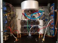
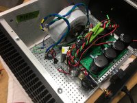
Edited to add Ben's answer to cap ? and a not so great pic from earlier. Yes, I am planning on cleaning up the wiring. Embarrassed to post it... LOL!

With my lack of understanding (so sorry while I learn) - the best way I can describe the wiring is that within the IEC module (provided from DIYAudio Store) there are two fuses. These are not rail fuses. So, I would not say that they're per channel. They're shared with the whole "amp". So 5A for both channels.
Out of the IEC comes two separate sets of mains cables (hot and neutral) for 4 total. Each pair goes to two separate blocks. After that the only common thing between channels is that I have the screen from the donuts run to a common point and the CL-60s from the PSU grounds run to the single safety ground.
Other than that literally everything else is separated and fully duplicated.
I have 8 x 18k uF caps for each channel. So 144,000uF per channel.
I hope that makes sense. It's all closed up now, but I can pop the top and take some pics. I have to open it again to do my final wire tying and clean up etc.
My personal guess is that if I were not so speedy on the switching on and off - I'd have been fine maybe even with the 2.5A slow blows I was originally using.
Edited to add Ben's answer to cap ? and a not so great pic from earlier. Yes, I am planning on cleaning up the wiring
. Embarrassed to post it... LOL!
Last edited:
Hi Ben and ZM -
With my lack of understanding (so sorry while I learn) - the best way I can describe the wiring is that within the IEC module (provided from DIYAudio Store) there are two fuses. These are not rail fuses. So, I would not say that they're per channel. They're shared with the whole "amp". So 5A for both channels.
Out of the IEC comes two separate sets of mains cables (hot and neutral) for 4 total. Each pair goes to two separate blocks. After that the only common thing between channels is that I have the screen from the donuts run to a common point and the CL-60s from the PSU grounds run to the single safety ground.
Other than that literally everything else is separated and fully duplicated.
I hope that makes sense. It's all closed up now, but I can pop the top and take some pics. I have to open it again to do my final wire tying and clean up etc.
My personal guess is that if I were not so speedy on the switching on and off - I'd have been fine maybe even with the 2.5A slow blows I was originally using.
you didn't clarified but I now think that you have one mains NTC per Donut , yes ?
that's OK , but you have one methodical and one temporary problem:
methodical - each Donut ought to have own mains fuse ; this way (as is) you need to have double value ( and even more ) of fuse , to have things functional
and it'll work properly only in case that both Donuts go Dodo in same time , which is extremely unlikely
temporary - NTC used as soft start device needs some time to cool off , so it can act again as surge limiting device
so , do not flip it fast after you powered it off
finally - simple math - you're having 2 Donuts of - what - 250VA each ?
living in country with 115Vac mains , that calls for (250+250)/115=4.34A fuse , which doesn't exist and you must use 5A slow blow , as minimal value ......... and even more likely 6A3
easiest way to make it properly , without really making a mess of back plate - find proper fuse holders ( and I mean proper , not those tiny thingies intended for pcb) , put them on base plate , so each Donut is having own fuse ( 2A5 to 3A15)
then put 10A fuses in existing IEC on back plate ...... as shortie
Last edited:
you didn't clarified but I now think that you have one mains NTC per Donut , yes ?
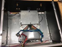
There are 2 per donut. See below and pic before in prior post. Hard to see, but each terminal block has the wiring below. Then there is one CL-60 coming off each PSU board ground and attaching to chassis/safety ground, then other leg of CL-60 to IEC ground per schematic. So, there are 6 total CL-60 in the build.

that's OK , but you have one methodical and one temporary problem:
methodical - each Donut ought to have own mains fuse ; this way (as is) you need to have double value ( and even more ) of fuse , to have things functional
and it'll work properly only in case that both Donuts go Dodo in same time , which is extremely unlikely
temporary - NTC used as soft start device needs some time to cool off , so it can act again as surge limiting device
so , do not flip it fast after you powered it off
Note with thanks. Not flipping on and off worked!
finally - simple math - you're having 2 Donuts of - what - 250VA each ?
400VA each. AS-4218
living in country with 115Vac mains , that calls for (250+250)/115=4.34A fuse , which doesn't exist and you must use 5A slow blow , as minimal value ......... and even more likely 6A3
easiest way to make it properly , without really making a mess of back plate - find proper fuse holders ( and I mean proper , not those tiny thingies intended for pcb) , put them on base plate , so each Donut is having own fuse ( 2A5 to 3A15)
then put 10A fuses in existing IEC on back plate ...... as shortie
So... if I try this exercise on my own. I need..
120 Mains at my house steadily. (400+400)/120 = ~6.7A
If I wire each donut, I need at least 3.35, so 3A5 can work. Then 10A will work in the IEC fuses. Since I'm trying to get two identical chassis set up, I can get the proper fuse blocks and install.
I looked online for some research and reading to understand, but I admit I am still confused a bit. Do I need one fuse per leg of the mains (hot and neutral) before the terminal blocks. See below for example pic. This seems to be the practice.

Then put two 10A in the IEC, correct?
Last edited:
in this type of electrical equipment , just one fuse in mains circuit is enough/adequate/appropriate
I will wire as such as soon as I get the proper holders and fuses.
Once again, thank you!

@Cal3713. You'll get it. There were a number of times I thought about starting over. I only put down the short list of my antics, frustrations, and goofs.
I'd love it if we could just flip some switches between amp boards
I am considering the motor caps. If I get vertical mounts for the toroids, I may have room. I'll need to do a bit more reading to understand what they do and how to install them. I'm still not quite sure.
Good luck with your troubleshooting!
To install the motor caps you just have to pull the power supply boards and then wire them to the final capacitor before the v+ and v- outputs (c6 & c8 on the diyaudio board). Just solder the wires to the pins that stick out of the bottom of the board.
You'll probably have to install vertically, but I laid mine down to have more space to access the boards.
I copied zm and used 50uf Ducatis (4.16.10.30.14).
Attachments
did you had some tunes through it , yet?
I have been listening for the last few hours in the main system. It is an exceptional amplifier.
I am still listening to my favorite music, singing, and tapping my toes. I cannot stop. I did not even look at the computer. A lot of people want to know how things sound. I find that things sound different to me, also... I am not very good at describing differences in sounds.
So I won't get too crazy with comparing with the M2x or Aleph J yet. Those amps deserve to be tried with dual mono. Also, my speakers and system may not make things sound the same as for someone else with their ears and brain.
Very brief - This amp seems much more "crisp" or "snappy" with exceptional detail. I can hear each piano key or string on a guitar in a chord, each voice in a chorus has its own place. The initial attack or strike with percussion announces itself before the sustain. To my ears and in my system it has the most detail presence of my three builds.
The Aleph J is a very easy amplifier. No one can hear anything harsh. It is the happy smooooooth friend that can make everyone smile.
The M2x is the chameleon. Change the input stage and change the sound.
I'll have many, many more years of happy listening with all of the amplifiers. I can't wait to get both chassis set up dual mono, so I can do some better comparisons side to side. Later, I will put in the F4 and F5 boards and try those too. I have them built, but they have no home yet
Once again
 THANK YOU!
PSU done and tested. CLC (4 chokes), decoupled rails, snubbers. Everything checks out. Where are the cinemags?
Attachments
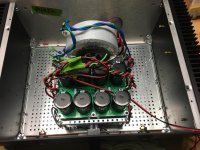

ZM you can see NTC and cap by the donut. The other plastic blocks after bridges and before cap board are snubbers. I put together Rs, Cs, and Cx, then shrink wrapped and put in the block.
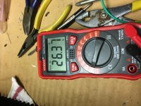
Is 26.37 unloaded rails in the range expected?
Is 26.37 unloaded rails in the range expected?
Attachments
- Home
- Amplifiers
- Pass Labs
- Babelfish M25, SissySIT - general building tips and tricks