Issues....
Hi guys, help!
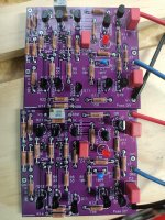
Just finished Wayne's boards and tried to adjust the as required. Disconnected R16 and adjusted till R6 voltage drop matched R14. These were just on 1.8v. Trouble is Q8 & Q14 got really hot. DC on the output was 45mv.
That was one board but the other is worse. Found that one of the 0v pads on the power supply board isn't connected, it has a solder pad but it's not connected to the 0v rail. This meant the amp board only had + - 19v no 0v. Corrected this but the output transistors got even hotter, to the point I couldn't hold them. There's also ~14v on the output so something big has happened!
Ideas?
Hi guys, help!
Just finished Wayne's boards and tried to adjust the as required. Disconnected R16 and adjusted till R6 voltage drop matched R14. These were just on 1.8v. Trouble is Q8 & Q14 got really hot. DC on the output was 45mv.
That was one board but the other is worse. Found that one of the 0v pads on the power supply board isn't connected, it has a solder pad but it's not connected to the 0v rail. This meant the amp board only had + - 19v no 0v. Corrected this but the output transistors got even hotter, to the point I couldn't hold them. There's also ~14v on the output so something big has happened!
Ideas?
Attachments
Hi guys, help!
Just finished Wayne's boards and tried to adjust the as required. Disconnected R16 and adjusted till R6 voltage drop matched R14. These were just on 1.8v. Trouble is Q8 & Q14 got really hot. DC on the output was 45mv.
That was one board but the other is worse. Found that one of the 0v pads on the power supply board isn't connected, it has a solder pad but it's not connected to the 0v rail. This meant the amp board only had + - 19v no 0v. Corrected this but the output transistors got even hotter, to the point I couldn't hold them. There's also ~14v on the output so something big has happened!
Ideas?
Q11 on the bottom board is mounted backwards..
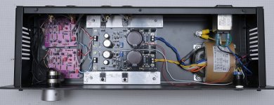
Install all parts as shown in post #1. Use P1 to set output DC offset to 0V. Q8 and Q10 do run warm due to the amount of current flowing through them.
Wicked! Thanks very much, appreciate the help. Great knowing there's help available if needed.... 99% of my projects go without issues but every now and then.......
Cheers Dave
Well…. I’ve been running Wayne’s line stage for a couple of weeks now, initially I thought it could be a bit clinical but no, its magic!
Hearing details that I’d miss with the Mezmorize buffer and what I’d call a more focused cleaner sound.
I really recommend if enjoy DIY audio, build this one and you won’t be disappointed. Nice and easy, ok I did make one stupid mistake but thanks to the helpful crew here it was spotted and fixed.
Big thanks to Wayne for sharing this design and the DIY Audio crew for your help with my various questions. Now what??????
Restore a Technics SP-10 and build a Pearl 2.

Re the SP-10 I have to echo 6L6's advice. I have been using these for many years now. They are far better than almost all other TTs and certainly better than all but the absolute best.
I have the purple coloured boards which are mono (so a pair of boards).
I could find some time today to use the TCP 2500 pot that I got recently to connect to my Wayne's preamp boards. I am confused a little bit with the wiring on the Wayne's line stage preamp board. I can see the pot has the markings like 1,2,C on in 2 rows. Looking at the shaft side how do I wire this pot to the input from RCA jacks of source (I do not have source selector for now, so only 1 source direct into the chassis) and the output from the pot to the Wayne's preamp boards.
I found the data sheet here - https://hfc-fs.s3-eu-west-1.amazonaws.com/s3fs-public/tkd_2cp25_datasheet_0.pdf
If someone can help me how to wire from the chassis insulated RCA input jacks to the pot and from the pot to the preamp boards, it would help.
One additional question is that I am powering my boards with a silent switcher so a very stable +/-15.1vdc. The ground (0) from the silent switcher goes to the GND marked near the output. But I seen that this GND near the output is being used as the ground for the output in most of the build pics that everyone has posted on the thread. I hope I am connecting the ground wires from the psu correctly as I can see V+, V- on both ends with output and GND in the center of each of mono boards.
Thanks
Last edited:
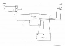
Thanks Jim much appreciated for the quick reply, the 3 that is listed on your diagram for the pot is actually the 'C' as on my TDK2500 pot right? I will try making this connection and see if I can get the volume attenuated properly ")
Also from which ground should I actually connect to the chassis or if this connection is required if I am making an integrated amp with the power amp also inside the same chassis?
Also from which ground should I actually connect to the chassis or if this connection is required if I am making an integrated amp with the power amp also inside the same chassis?
- Home
- Amplifiers
- Pass Labs
- Wayne's BA 2018 linestage