I'm sure there will be other recommendations...Not sure about "definitive recommendation" seeing this is all DIY, but...
Here's what I used (thanks 6L6):
DIY PCB - Bipolar (opamp) power supply | eBay
BOM at the bottom of this page:
LR Phono Preamp
Worked out perfect. Not too $$ to build. Has a fuse onboard—intelligent power switch setup—simple to add a power LED. Could have easily gotten 24VDC+/- out of it with resistor tweaks (R4, R6—values will not match due to circuit design). As is I tweaked it to around 18VDC +/-. It also fits in a 1U as speced in BOM as long as you use 1" heatsinks on the regulators.
513002B02500G Aavid, Thermal Division of Boyd Corporation | Fans, Thermal Management | DigiKey
See posts #919 and #932
Last edited:
Finished the boards now waiting for PS board and parts. Re read a few posts and read something about setting trim pot, was I meant to do it before the boards were fully populated or do I just for minimum DC offset at the output?
There was comment that this method (DC offset) might not give the best result.
Correct or did I read it wrong? (Very possible!)
There was comment that this method (DC offset) might not give the best result.
Correct or did I read it wrong? (Very possible!)
I'm sure there will be other recommendations...Not sure about "definitive recommendation" seeing this is all DIY, but...
Here's what I used (thanks 6L6):
DIY PCB - Bipolar (opamp) power supply | eBay
BOM at the bottom of this page:
LR Phono Preamp
Worked out perfect. Not too $$ to build. Has a fuse onboard—intelligent power switch setup—simple to add a power LED. Could have easily gotten 24VDC+/- out of it with resistor tweaks (R4, R6—values will not match due to circuit design). As is I tweaked it to around 18VDC +/-. It also fits in a 1U as speced in BOM as long as you use 1" heatsinks on the regulators.
513002B02500G Aavid, Thermal Division of Boyd Corporation | Fans, Thermal Management | DigiKey
See posts #919 and #932
So what were the values you used to set the 18V?
Cheers
So what were the values you used to set the 18V?
Cheers
Hi, if you look at the schematic he notes 13.7K for 15V (typo there, it should say “R6”)... I needed different values for each side to get the output more balanced, and I didn’t make proper notes, so you will need to experiment, but I recall that R4 was around 17K and R6 around 18K and change. You can see that I have a couple of resistors in series...
Report back on what you discover! Ha! I’ll make a note then.
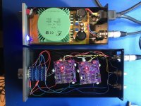
I started on this project a year ago and got about 70% done. I had all of the parts but only one of the two boards that I built worked. So somehow I forgot about it (or ignored it) for about 11 months. But I finally got back to it and a blast from a hot air rework station gun aimed at a suspicious looking SMD part got the second board working.
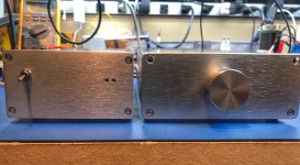
And finally, though it isn’t particularly attractive, it is done and it works.
And finally, though it isn’t particularly attractive, it is done and it works.
Attachments
Last edited:
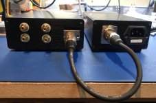
I think you are being hard on yourself. It actually looks quite nice to me. What power supply are you using? I am looking for something like that for another application.
I agree! Looks great... give us some more details!

Looks quite nice to me.And finally, though it isn’t particularly attractive, it is done and it works.
") Neat and compact. Well done!
Neat and compact. Well done!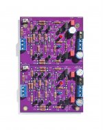
- Home
- Amplifiers
- Pass Labs
- Wayne's BA 2018 linestage