HiI can say it is VERY easy to change the gain, just one or two resistors are changed. If I get my measurement system sorted I could make some measurements.
Would you change the value of R16 or R17 ? One of the 2 probably have to remain the same.
I’d like to add a DPST switch so I can go from a gain of 3.7x to 10x.
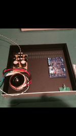
Pic of my slow progress...
Thanks
Eric
Attachments
Last edited:
@e_fortier
Exactly.
See here. You can also see my measurements in that link, just a few posts up. Confirms 10X gain. R16 stays constant.
Best,
Anand.
Exactly.
See here. You can also see my measurements in that link, just a few posts up. Confirms 10X gain. R16 stays constant.
Best,
Anand.
Last edited:
I will admit to being a total idiot, but I still could use some help.
My problem was that I did not have the jumpers installed that connect the two independent power supplies together at a common ground, so, problem solved.
I thought. When I turned the power on, one of the 10R power resistors got really hot, The other one's OK. Pulled the plug to keep it from melting down, so I never had a chance to check the output voltage on the presumably good side.
The frustrating thing is that this PS was working fine before I installed it, although I was measuring each independent half separately which explains the jumper issue. I did verify that the 1.5 mm thick polycarbonate sheet is intact so there's no electrical contact with the case on the bottom side.
Any ideas on what might be causing this malfunction? Any parts upstream or downstream of the overheating resister I should be checking?
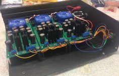
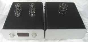
Yesterday I did the inital firing up of my Waynes 2018 and to my amazement it worked on the first go! (see photo). Now I have a question regarding the adequacy of the power supply. I used an Antek 0212 which is rated at 20VA and 12V dc. It is giving me 14.5V dc coming out of the power supply. Would I gain anything by going to a larger 50VA 15V Antek? More gain? Any other sonic advantage?

sndlvr:
I believe 6L6 reported that the ideal voltage for the BA2018 was in the +/- 18-19 VDC range. RickRay appears to be right -- your power supply looks unregulated. If you want to use that, a transformer with 14 VAC secondaries should net you just over +/- 18 VDC. A transformer with 15 VAC secondaries will net you roughly +/- 20 VDC, which would also be fine. Or switch to a regulated power supply like the VRDN, which would allow you to dial in the DC voltage with precision. Either approach works.
Regards.
Thank you! Will get the bigger transformer and also read up on that VRDN power supply. Sounds like a great idea. Ideally set up as an external power supply to power various DIY builds, saving money on future power supplies and also allowing smaller casses. Kudos to Mark Johnson
A further question on the overall design of the Waynes 2018. It is set up to have balanced inputs but single ended outputs. I'm curious why it was done this way. Anybody know? I am going to add the option for eiither single ended inputs or balanced, which I think requires a switch as indicated in this schematic.
A further question on the overall design of the Waynes 2018. It is set up to have balanced inputs but single ended outputs. I'm curious why it was done this way. Anybody know? I am going to add the option for eiither single ended inputs or balanced, which I think requires a switch as indicated in this schematic.
sndlvr -
BA 2018 is another discrete op-amp, of which there are a zillion variations from super simple to quite complex. You have an inverting input, and a non-inverting input, and an output that is the difference between those two input signals. So they lend themselves to having a balanced drive source, but you can just ground the unused input and the circuit will happily output the difference between the two.
BA 2018 is another discrete op-amp, of which there are a zillion variations from super simple to quite complex. You have an inverting input, and a non-inverting input, and an output that is the difference between those two input signals. So they lend themselves to having a balanced drive source, but you can just ground the unused input and the circuit will happily output the difference between the two.
Last edited:
I was contemplating this option too but I don't believe it's as simple as adding a switch. There are a couple of resistor changes too (which you can find out about in this thread... somewhere!).A further question on the overall design of the Waynes 2018. It is set up to have balanced inputs but single ended outputs. I'm curious why it was done this way. Anybody know? I am going to add the option for eiither single ended inputs or balanced, which I think requires a switch as indicated in this schematic.
As well, I had asked about the bias adjustment. It occurred to me that the bias adjustment might change between balanced and unbalanced operation and that resistance might need to be changed too if you were going to switch from a balanced in to an unbalanced in with your switch.
As well, you probably have to get fancy with the attenuator wiring to change from 2-gang to 4-gang.
What I had had in mind was a preamp that catered to a Pearl phono stage and a DAC with balanced outputs. The BA2018 would feed an amp with an unbalanced input.
Hope this helps.
@mhenschel Giving it a bit more thought my notion is to go with balanced inputs only and just get a pair of rca to xlr external adapters for the occasions when i want to accomodate an RCA input. For volume I will go with two ALPS stereo attenuators which give the added benefit fo balance control though independent volume regulation of each channel. I'm don't really see where resistors come in to play, but if you can point that out to me I would be much obliged.
Will get the bigger transformer and also read up on that VRDN power supply. Sounds like a great idea. Ideally set up as an external power supply to power various DIY builds, saving money on future power supplies and also allowing smaller casses.
sndlvr:
One more thought: if you're going to put a dedicated "universal" power supply in a separate chassis for various preamplifier and other low current-demanding projects, at very least consider making it dual mono. I built a two-chassis BA2018 for my main system a few years ago that includes three power supplies: dual mono for the BA2018 and a third supply for ancillary demands. Ridiculous but satisfying.
Regards,
Scott
Attachments
many thanks! I found the post in question from Win. It is number 263 of this thread.
Post in thread 'Wayne's BA 2018 linestage'
https://www.diyaudio.com/community/threads/waynes-ba-2018-linestage.329240/post-5699074
I understand that this just gets me to accommodating balanced inputs, but the outputs are still single ended, unless you add two more boards, and complete the conversion to fully balanced.
@SRMcGee i’d be interested in your thoughts about the trade-offs when going to external power supplies. We introduce connectors and cabling, which raise the potential of losing some of the benefits gained elsewhere in the system. What kind of connectors and cabling did you use? And do you feel there are any compromises to sound quality ultimately?
sndlvr:
I think the benefits of external power supplies greatly outweigh the detriments. Understand that I'm no engineer -- take my perceptions with a huge grain of salt. Transformers and power supplies can make noise in the audible spectrum; distancing them from line level audio signals reduces the level of noise and audio degradation. It also looks cool. The only downsides I've found are cost (an extra chassis, fancy millwork and an umbilical comes at a price) and the extra shelf space needed. I make the umbilical cables to order (and enjoy doing it); you might find this thread interesting: https://www.diyaudio.com/community/threads/build-up-umbilical-cable.379909/. Also, I usually include 0.1 uF caps in the preamp to filter any noise picked up in the run from the power supply chassis.
As cliche-slingers will remind you, your mileage may vary.
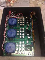
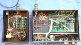
Attached below are photos of three of my two-chassis preamplifier projects.
Regards,
Scott
I think the benefits of external power supplies greatly outweigh the detriments. Understand that I'm no engineer -- take my perceptions with a huge grain of salt. Transformers and power supplies can make noise in the audible spectrum; distancing them from line level audio signals reduces the level of noise and audio degradation. It also looks cool. The only downsides I've found are cost (an extra chassis, fancy millwork and an umbilical comes at a price) and the extra shelf space needed. I make the umbilical cables to order (and enjoy doing it); you might find this thread interesting: https://www.diyaudio.com/community/threads/build-up-umbilical-cable.379909/. Also, I usually include 0.1 uF caps in the preamp to filter any noise picked up in the run from the power supply chassis.
As cliche-slingers will remind you, your mileage may vary.
Attached below are photos of three of my two-chassis preamplifier projects.
Regards,
Scott
Attachments

Not the way I wanted to bring this thread back up to the top...
I was using the alternate TTA004BQ / TTC004BQ (& 15 ohm R11 & R12, removed R23/C4, changed the value for C1 etc. as per instructions). I merely transposed the output pair... Ooops.
There was the `release of smoke...' or at least I could smell something get hot in the <1Second that was power was applied before I noticed...
I assumed the output pair of transistors are smoked and pulled them and will order some more. In the meantime I put a couple of spare KSC1845 nd KSA992 in their stead. I appreciate they would likely also cook given the lower values for R11 and R12, but wanted to see if there was at least some functionality on their way out the door. Unfortunately I note the LEDs no longer light. So apart from Q8 & 10 (and I will also replace R11 & 12 and the LEDs, is there anything else that I may have smoked (all assuming that I didn't make another error...). And is there any simple measurement I could make with a DVM to confirm?
yours chastened of WA,
- Home
- Amplifiers
- Pass Labs
- Wayne's BA 2018 linestage