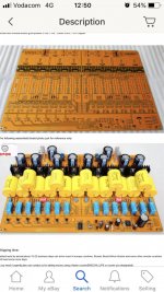
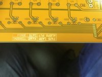
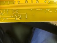
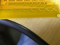
Hi all. I purchased a 1.7 preamp board off eBay which took 9 months to arrive, but is now here. I have been drawing up a parts list, but see that there is a chip connecting to the relay ladder, and don’t know what this is. Has anyone built one of these before, and if so, could you tell me what this chip is. The supplier has not sent me the schematics and am battling. Any assistance would be most appreciated. Thanks
What's the front-panel control system?
If individual-source push-buttons it's probably an octal flip-flop of some sort. (Although the pin-out doesn't look like any flip-flop I know of.)
If source-up/source-down push-buttons it's probably a PIC of some sort (for which the pinout makes sense). But then you're going to have to program your own PIC if they didn't send you one.
If remote-control, then it's probably also a PIC.
If it's a selector switch then I'm not sure why you'd have a driver at all (note that there are also BJT drivers for the actual relay coils).
???
Have read a lot, but boards seem a bit different, and don’t have the relay volume on
Hey Brendan,
Did you mean by the above that you "don't have the relay volume version of the board"?
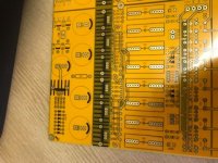
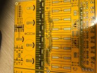
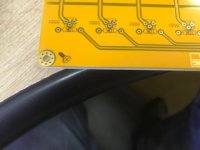
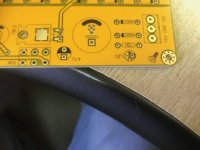
Because it appears that you do. That logic isn't doing source selection, it's doing volume control. The 50K pot (6 holes at the front of the board) is hooked to the voltage input of the analog-to-digital converter (I'd say NPower was correct and that it's an ADC0804). The digital output then drives the relays; each relay must be connected to a resistor that's a multiple of 2x or 10x or something from the previous resistor.
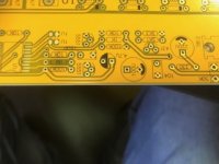
The two 5551 BJTs appear to be implementing turn-on delay. One holds the INTR down for a short period (resetting the volume to 0), and the other holds the READ down for a longer period (after which the volume pot will be read).
The 7812 is a 12V voltage regulator supplying power to the relays and the volume pot, while the 431 is a shunt regulator supplying 5V to the ADC.
So it should be pretty easy to put together. No PIC or PIC programming required.
Cheers,
Jeff.
- Status
- This old topic is closed. If you want to reopen this topic, contact a moderator using the "Report Post" button.
- Home
- Amplifiers
- Pass Labs
- eBay aleph 1.7 board