Just wanted to try my remaining Semisouth SJEP120R100 as Q2 in the meantime I assemble the left channel, I am astounded how much is improvement, as a shunt this NOS Jfet also provides much benefit, when music gets louder mantains the same open field projection signature as do in smooth passages. Timbricaly less distortion. Very impressive
still cold, burned in almost one hour. Not having on hand any more powerful mosfet to compare, I have only a chance for tomorrow to try: Fairchild FQH44N10. Will be that compatible for only 23v psupply? Hope no smoke or burn.
still cold, burned in almost one hour. Not having on hand any more powerful mosfet to compare, I have only a chance for tomorrow to try: Fairchild FQH44N10. Will be that compatible for only 23v psupply? Hope no smoke or burn.
[ munch ]
To do:
- DONE - try a variety of bias points for Q1 Drain voltage (adjusted by P1) and see how H2 and H3 change - is there a sweet spot there?
- DONE - include the PHASE of the harmonics in the data logs, as that can be important (per Nelson Pass interview (page 2, between the photos: Nelson Pass: Circuit Topology and the End of Science | Stereophile.com ), positive phase for H2 is "in your face" where negative phase for H2 expands the sound stage front to back)
- DONE - look at changes to R14 and see if it impacts the PHASE of the harmonics, post 315 implies it does (negative phase for H2 is presumed)
- DONE - verify my R16 isn't cutting too much voltage (3k, others are using much smaller values), as baseline current thru Q4 is about 4mA
- check capacitor on R12, see if that impacts harmonics and their phase (prior post implies it might decrease H3 or impact phase)
- do research on IRFP044 and 440 as possible candidates for Q1 or Q2 positions
[ munch ]
- increase bias current (start with R4a of 2 ohms - from TA's mods - < no - start with Loudthud's mods >) and see what changes
dfoulk
I found it interesting that my messing with my 5k pot (R14) did absolutely nothing to the phase or magnitude of the harmonics as I went up from the 1k nominal value. Perhaps mine doesn't have the same capacitance yours did? Or perhaps it is because I'm using resistors for a load, not actual speakers? Perhaps I will have to add a cap to my setup to see what you heard... Now if I went lower, I could force clipping, but that's not what I wanted to accomplish.
TungstenAudio
I tested the C2 capacitor, and swapped a new (verified good) Nichicon RNL 1000uF back into the circuit and it worked very nicely. Somehow I either got a bad cap, or managed to kill it (how?). Nice to have it back to a configuration largely based on your upgrade list.
From my list of things to do
- Bias and harmonics
I tried different bias points to look at the phase and magnitude of H2/H3 with a power supply voltage of 40v. The results were interesting. In each test run, I set the bias voltage for the amp, then I adjusted the input voltage until I had either 3%THD or 1%THD (depending on the series). If the bias went low enough, H2 started to drop and H3 started going up, but that was well off the 1/2 voltage point. In the 1% case, it was near 15v, and at about 18.5v at 3%, with visible clipping starting to deform the waveform (output waveform was 12.6v rms).
The phases for H2 my amp was around +90, going slightly higher at high bias voltages and slightly lower with lower bias voltages (in the 80 degree range at 18v, barely going over 91 at 22v).
H3 was slightly positive at 3% THD, but slightly negative at 1%. H3 was more complex, especially with 3%, where it was maximum (17 deg) at about a half volt below V/2 (19.3v), and decreasing as the voltage moved either higher or lower. For 1%, it started about -19 degrees at 22.5v, and slowly decreased to -7 degrees at 17v.
In short, I was somewhat disappointed at how this turned out, as the adjustments made very little difference to how the harmonics moved, either in magnitude or in their phases.
- Other things that were done include checking that my choice of values for R16 wasn't the cause of any problems. With my 40v supply, R16 drops a little over 13v, meaning 26v or so are available, a little more than it would see with the 24v supply, so nothing should be all that different.
- Since my setup is a little different than others, some steps marked DONE will be revisited when I can mod my setup to be a little closer to what they have used to see if I can replicate their results (specifically R14 and capacitance).
- Harmonic wrestling and bias current increasing
The next step will be to optimize the harmonics by trying Loudthud's resistor choices for R1-4, and then to increase the current back to useful levels (via R15/R8).
For me, that means R3/4 will be a 1.5/2.0 in parallel (0.85 ohms, replacing the two 0.68) and R1/2 will each get a piggyback of a 1.5 (0.18 ohms). Both values are a tiny bit large (his recommendation: 0.82 & 0.15), but it should get me close. All the resistors I have are 3W each, and until we get over 2.5A, everything should be good.
Then I will have to experiment with R15 to get the current up to somewhere in the 1.6 to 1.7A range and get back to testing, starting with seeing how the harmonics look at 1W, then at 1% and see if we don't get more headroom out of this layout and power structure. Then back to the tweaks on the list, to see what can be done to the phase of the harmonics.
I was also disappointed with the power output with a 40v supply. At 3%, I could get all the way to 19W. However, I was still limited to just a hair under 8W at 1% THD. Time to get serious about THD, while still keeping a bit of H2 bias, to keep with the basic design and character of the amp.
Drat. I got so focused on bumping up the power and looking at the harmonics that I completely forgot to see what things looked like at 1W... Chasing power without ensuring the fundamentals are properly set up is a fool's errand... Seems I'm having to re-learn a lot of basics. Perhaps I'm enjoying this too much. 8)
The power output you’re getting is very comparable to the Zen v4, with an internal voltage of 42V after the CapMx. This circuit is not the most efficient, but single-ended class A has a wonderful sound.
The sweet spot for the bias voltage usually seems to be around V/2 +0.5 to V/2 +1.0, set to produce a slightly asymmetric waveform at the onset of clipping.
The sweet spot for the bias voltage usually seems to be around V/2 +0.5 to V/2 +1.0, set to produce a slightly asymmetric waveform at the onset of clipping.
Attachments
Let us know!
Jordi,
The 44N10 will be fine. I plan to try the IRFP044 for both Q1 and Q2. It is nice as Q1 with a IRFP140 for Q2. Then I am going to try the 44N10 for Q2 with the 044 for Q1. I have a IRFP440 also, that I might try, but as Tungsten noted, it is very similar to the IRFP240 on paper, but sometimes paper is
unreliable, and it still leaves my curiosity alive and well! Just get weary of
constantly tearing stuff apart, but soon will arrive at a settled conclusion.
Just wanted to try my remaining Semisouth SJEP120R100 as Q2 in the meantime I assemble the left channel, I am astounded how much is improvement, as a shunt this NOS Jfet also provides much benefit, when music gets louder mantains the same open field projection signature as do in smooth passages. Timbricaly less distortion. Very impressive
still cold, burned in almost one hour. Not having on hand any more powerful mosfet to compare, I have only a chance for tomorrow to try: Fairchild FQH44N10. Will be that compatible for only 23v psupply? Hope no smoke or burn.
Thanks Erik, I will buy C2M0280120D to try as Q2 and then share here.
Thanks Den for confirm, tomorrow I will safety place 44N10 as Q2 to compare against Semisouth. I will left 2 days for settlement.
Is nice to know you have also 44N10 for comparison, please post results anytime you may try, against Mosfet IRPF series.
Thanks Den for confirm, tomorrow I will safety place 44N10 as Q2 to compare against Semisouth. I will left 2 days for settlement.
Is nice to know you have also 44N10 for comparison, please post results anytime you may try, against Mosfet IRPF series.
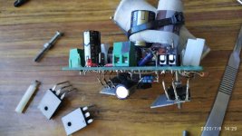
Den, are you doing? you are dealing like me with same Aca PCB with centered mosfet pins just in middle of the board, also a hole to screw the mosfet?
Today I confirmed IRPF240 as Q2, has a similar degradation as in Q1 (already reported), as a Q2 is unable to manage the bass frequencies, almost muted them, remaining a shade, around midbass, which is unfocused and without detail. Damage is overall, high frequencies have a harsh timbre not pleasant.
Of course this is after hearing 44N10 as Q2. I can't praise high enough that so called 'enhancement mode power mosfet' all I can read in their specifications sheet is right: ''This advanced MOSFET technology has been especially
tailored to reduce on−state resistance, and to provide superior
switching performance and high avalanche energy strength. ''
FQH44N10 sound is plenty of body and bass and dynamic sound, is a very great upgrade to the ACA considering price-performance cost, still don't know in absolute terms, as still Silicon Carbide (SiC) Jfet transistors from SemiSouth are still better in detail resolution, as I heard yesterday late night just after the mosfet IRPF240.
Now the pain again change another time to 44N10, but is my fault as I removed yesterday Sunday before complete the time burn in.
Jordi
Attachments
still testing
Hi Jordi,
Yesterday I tried the 44N10 with a 044, and I like better the 140 as Q2 and the 044 as Q1 over the 44N10 as Q2. For me, the N10 seems to punch up the midrange which was not bad, but I still liked the 140 better. I read the pdf that Tungsten posted on the Zen4, and in that particular circuit, Mr. Pass preferred the 044, which I had stumbled upon before reading his comments. Today will try 044 for both Q1 and Q2. The high transconductance of N10 at 31 perhaps not so good with interacting with my other mods to the amp circuit, and the 140 has 9.8, so N10 has triple that amount. The 044 is 16 transconductance, perhaps a better combo for me, but will see and post later.
done for now....
Had enough soldering and unsoldering.
I am holding with a IRFP044 for Q1 and Q2. Sounds very balanced top to bottom. Running at 29 volts on the rail, and 15.25 volts on the drain of Q1.
Have 2K for R14 with a .33uf parallel, which measures out to .43uf and 2K.
Feedback R12 is 332K with 20pf polystyrene paralleled. I do have 150 ohms for the gate stopper on Q1 and Q2.
It sounds pretty darn nice to me on my DIY open baffles. Never did try the IRFP440, but maybe someday. It makes a rough day for the circuit boards to be constantly soldered and unsoldered. No complaints with the sound that I have now, very rich and detailed")
Had enough soldering and unsoldering.
I am holding with a IRFP044 for Q1 and Q2. Sounds very balanced top to bottom. Running at 29 volts on the rail, and 15.25 volts on the drain of Q1.
Have 2K for R14 with a .33uf parallel, which measures out to .43uf and 2K.
Feedback R12 is 332K with 20pf polystyrene paralleled. I do have 150 ohms for the gate stopper on Q1 and Q2.
It sounds pretty darn nice to me on my DIY open baffles. Never did try the IRFP440, but maybe someday. It makes a rough day for the circuit boards to be constantly soldered and unsoldered. No complaints with the sound that I have now, very rich and detailed


I'm using the IRFP250 Mosfets in my first pair of MoFo boards. These are the standard one recommended for the project. Of course I want to try something different, so I have a pair of FQH44N10 devices reserved, plus a pair of IXTH64N10L2 to try as well on another pair of boards. I've included an ACP+ gain stage inside the chassis to boost the input signal a bit.
The Serbian package is the Singing Bush kit from our Mighty Zen Mod. I intend to thoroughly abuse them. Don't tell him that. Think Melting Bush
The Serbian package is the Singing Bush kit from our Mighty Zen Mod. I intend to thoroughly abuse them. Don't tell him that. Think Melting Bush
Since the ACA is not my first amp build, simply the first NP class A design, I decided to have some fun upgrading a few of the parts. I was careful to make sure that the new parts were straightforward drop-in replacements for the originals, with one exception as noted below.
<SNIP>
There is a part 2 to the process, which I'll post next.
Hi Tungsten,
I'm new to the forum and the ACA amps, and am preparing to start my first ACA build, on ACA 18. I found your first 3 posts at the beginning of this thread using premium parts to be of interest, and had a question for you. I note that you are using your amps configured as bridged monoblocks. Would the upgraded premium parts you have listed in your posts also be useful if one is building a single stereo amp of ACA 18? Sorry if this question has already been asked, I just joined the forum a couple days ago and have not had time yet to read through all the informative and voluminous posts!
Thanks in advance for your help.
Cheers,
Stephen aka PC
- Home
- Amplifiers
- Pass Labs
- ACA amp with premium parts