Today I heard for first time my new choke I custom ordered 2k4 copper resistance inductor.
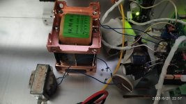
Not being scarce, I asked for best core material, and got 4C amorfe core. See photo atch. below is big one compared to permalloy on the left. And glad I do, since first listen I noticed big difference, for the better of course, then took back and forth several times, to take account why. Less sibilance in vocals and much more dynamic uncongested sound. Using amorfe core is bulky and expensive, but shares how much potential is concealed below the humble 1k R14 resistor.
Not being scarce, I asked for best core material, and got 4C amorfe core. See photo atch. below is big one compared to permalloy on the left. And glad I do, since first listen I noticed big difference, for the better of course, then took back and forth several times, to take account why. Less sibilance in vocals and much more dynamic uncongested sound. Using amorfe core is bulky and expensive, but shares how much potential is concealed below the humble 1k R14 resistor.
Attachments
Quick question.
LSK170 comes in different IDSSs: 2.6-6.5mA, 6-12mA, 10-20mA, and 18-30mA.
Does this matter for the ACA? I was going through my parts stash and I found 4 LSK170, all in the 18-30mA range. Can I use them as is, or any modification could allow for that?
If the P1 pot adjustment cannot bring the Voltage down to the proper level, change the value of R9 lower to perhaps 680 or 470 Ohms. Check that Q4 is not running too hot.
Singin
New boards up and cooking. Running on 29.2 volt rails, and 15.30 volts on drain of Q1. Q1 is a 044, and Q2 is a 140. R12 is 332K, R5,6 is 150 ohms. R14 is 2K with a parallel .33uf. When I measured the capacitance and the 2K resistor together, it measured .43uf, but on my open baffle speakers, this comfiguration is great. I do not hear the highs being rolled off. R11 remains 10K. I used all 1% Dale resistors for everything except R13, the LED voltage dropper, and used 33K regular metal film.
For C1, I used a monster Nichicon 4700uf 63 volt, level three. It was like putting an elephant in a shoebox, but it sounds richer than the regular Nichicon grade 1. I have a 22uf Muse for C3, and everything by-passed with a 100 volt .1uf WIMA, except on the 4700uf, I added 2 .33uf in addition to the .1uf on the underneath side. I am not changing nuthin from now on, just going to listen. I used a 250 ohm dropper on Q4.
Soundstage is wider and deeper, bass is incredible. Ok, thats the evening report!
Jordi
Hooray
New Good sound is always an exciting discovery!!!
Will post again after I get my new boards put together with changes.
Den
Den thanks! and congrats as well, getting your amp also tailored to your system!!
Yesterday I listened till late, from the Semisouth SJEP120R100 transistors
already cooked and today I reinstalled the original Q1 IRPF240 to confirm the degradation.
Is that to improve the brain gets used to and betrays.
At the moment what I'm hearing - the same as yesterday - is not projected in front of the speaker.
The semisouth feared they were fake, I saved half. As soon as it sounded I was calm, it didn't improve much, but it projected infront. They were authentic.
They took longer to roll than the toshiba, (24h). Those longer, two days minimum.
Every day was getting better, but with doubts about whether the new choke in R14 was also cooked at once.
So today I will clarify and honestly I could turn off right now, it is clear that the noticeable improvement was from Semisouth.
In addition to sound projection, it has been improving in separation of instruments, extension of bass...
All about the amplifier has been satisfactory. With the final cherry on the cake...
Stupid question, but the input capacitor can be reduced. Whay stay with an electrolytic? My ACA kit has 10 uF bipolars (Muse from Nichichon). The original design just is a normal polarized one.
On the other hand I tried a 1 uF mylar cap on the input of the ACA, and the circuit is stable and undistorted from (far) below 5 Hz to above 1.200 KHz (yes 1.2 MegHz).
Are there do's and don'ts I miss?
On the other hand I tried a 1 uF mylar cap on the input of the ACA, and the circuit is stable and undistorted from (far) below 5 Hz to above 1.200 KHz (yes 1.2 MegHz).
- So why use an electrolytic?
Are there do's and don'ts I miss?
Probably the main reason that 10uF electrolytics were used in the ACA is that the particular one used (Elna Silmic II) were small and of known good sound quality. This made it easy to put together a simple kit that would be relatively inexpensive, but still produce an amp that was easy to assemble and sounded great for new DIY enthusiasts.
Simple.
The smaller cap positions can certainly be tweaked to one's inclination and content. I might suggest a 2.2uF, 50V Nichicon ES series bipolar cap in the C3 position, though I have continued to use the 10uF Elna Silmic II that was part of the original kit. Film caps tend to be physically large, and are not always a good substitution for that reason. If you can find a 1.0uF, 63V polypropylene or PET cap that fits reasonably well, then that may be worth trying. The C4 position is a good place to try something different, especially if you have managed to add R16. I like larger value (100uF) organic polymer caps that have a small diameter case and close lead spacing for C4.
Hi Den, I placed SJEP120R100 only in Q1. May have marginal benefit also on Q2, but if any, not deserves the extra expense there.
Concerning the capacitor you add to R14 (0,33uF)
I was hesitant from the beguinning to try. Adding components to the smart N.Pass circuitery.
You know me, I was happy actually further reducing components to their desing. But your suggestion bypass R14 with an small cap seem easy to try (can be done from the speakers connections). I have done today is St. Peter day, not working in my town.
I tried different small capacitor values, all russian teflon, but in the end the much preferred in my case was the smaller at only 10nF.
That not meaning has an small benefit, no no, it is very important find, giving the sound more 'loudness' but at the time more airy and treble extension.
Jordi
The stock kits are back in the store!
Amp Camp Amp – diyAudio Store
Cool new labeled rear panel and wiring to make it easy to select 2ch stereo or
Monoblock balanced, bridged or balanced.
Amp Camp Amp – diyAudio Store
Cool new labeled rear panel and wiring to make it easy to select 2ch stereo or
Monoblock balanced, bridged or balanced.
These kits are great to work with. Buy two ")
One of the best ways to 'upgrade' the ACA is still to bridge the two channels inside one chassis, then use a pair as monoblocks. The type of bridging that works best will depend on your speakers, and it is easy to try the different types.
One of the best ways to 'upgrade' the ACA is still to bridge the two channels inside one chassis, then use a pair as monoblocks. The type of bridging that works best will depend on your speakers, and it is easy to try the different types.
IXFB82N60P
Hi there Mr. Wrath,
I don't know that much about it, but those are kinda pricey, around $20 a piece.
I had asked Tungsten what he thought about the IRFP440, a beefier selection than the IRFP044 that I am currently using for Q1, with 29 volt rail voltage, and he suggested the FQP44N10, as he was using them and was pleased. I like the IRFP044, but I think I will try the IRFP440 just to see. They are around $3 a piece, and are 500 volt rating. If your pockets are deep, there is the Semisouth SJEP120R100,
at $100 a piece, supposed to be very nice, used by Mr. Pass in some of his highly regarded amps. I have also heard from Jordi that they really sound good in his ACA for use as Q1. Of course they are not made anymore, so the high prices, and beware of fakes. When I try the IRFP440 for Q1 and the current used IRFP140 for Q2, I will post what I hear.
Den
The IXFB82N60P is one of a new series of parts that have been designed for switching applications, rather than linear. It has a different set of design tradeoffs from the IRFP440, which is also a newer part. Where the IRFP440 has a moderate input capacitance, low gate charge and low transconductance, the IXFB part has very high input capacitance (23 nF) and high gate charge in order to obtain its high transconductance. Both parts would be rated at about 140V for continuous Vds, rather than 500V or 600V for pulsed operation.
The IRFP440 might be Ok for linear operation, but its low transconductance doesn't offer any advantage, at least on paper, over the IRFP240 or IRFP140. The IXFB82N60P, with its extremely high input capacitance, is probably not suitable for the ACA. Certainly not for the Q1 position, though it might work for Q2, but with different sonic character. Remember that Q2 in the ACA functions as part of an interactive current source, so its dynamic behavior is important.
These are examples of some of the different tradeoffs that are inherent in the fabrication of Mosfet transistors. High Vds capability and high current both tend to result in high gate capacitance and high gate charge. High transconductance and low Rds-On are similar. Optimizing for those parameters extracts a toll in other areas of performance that we find desirable for audio.
There are other amplifier designs that make good use of the newer physically large Mosfets. Probably the best example is the Pass Labs XA25, which has enjoyed great critical and commercial success. Though its exact design remains a topic of much speculation, we can safely say it uses IXFN140N30P and IXTN40P50P transistors. Another design is the BA2015 50Watt Shade amp which uses a pair of IXFN140N20P Mosfets. These are examples of big "hockey puck" transistors that require very different designs to drive them properly. The front end of the XA25 is a power amplifier in its own right. The BA2015 hockey puck amp uses a transformer to drive the lower IXFN140N20P, and in turn requires an input stage (or preamp) of very low output impedance. The simple design of the ACA cannot support such large transistors.
mosfets
I must say that I am just curious about the sonic character of the IRFP440, and it
is an inexpensive part. I know from the past that every transistor does have it's own sonic character, and mixing them can sometimes give you something different that you would not be able to obtain otherwise. Kind of like the taste of the right amount of lemon in your sweet iced tea Also, I am experimenting with the specific sound of my own home brew open baffle speakers, so what I hear may not be applicable to everyone. There are parts that just won't work in the ACA circuit, but I sure enjoy the exchange of ideas and information from knowledgeable experimenters!
I must say that I am just curious about the sonic character of the IRFP440, and it
is an inexpensive part. I know from the past that every transistor does have it's own sonic character, and mixing them can sometimes give you something different that you would not be able to obtain otherwise. Kind of like the taste of the right amount of lemon in your sweet iced tea
Also, I am experimenting with the specific sound of my own home brew open baffle speakers, so what I hear may not be applicable to everyone. There are parts that just won't work in the ACA circuit, but I sure enjoy the exchange of ideas and information from knowledgeable experimenters!R12 - feedback?
If I understand correctly R12 is the feedback resistor here. I find another member, xrk971’s use of carbon film resistors for the feedback very interesting and wonder if someone here has considered or tried it for the ACA yet? See the comment from another thread:
If I understand correctly R12 is the feedback resistor here. I find another member, xrk971’s use of carbon film resistors for the feedback very interesting and wonder if someone here has considered or tried it for the ACA yet? See the comment from another thread:
I was always fascinated with X's measurements using carbon resistors v. metal film resistors in the feedback networks of the Alpha. He demonstrated conclusively that metal films bring up the third harmonic over the second; the carbons do the opposite.
Best sounding amps have a monotonic decrease of successive harmonics, and the more linear, the better. This is from Jean Hiraga in the 60s - nothing is new and demonstrates how the marketing speak drives the equation rather than the truth.
Cheers,
Hugh
carbon resistor
Maybe this phenomenon is why Tungsten has found that a small capacitor added in parallel to R12 improved the sound of his ACA when driven hard. Perhaps the capacitor has reduced the odd harmonics in a similar way to the carbon resistor?
Just a guess, I do not have the equipment to test the idea
Maybe this phenomenon is why Tungsten has found that a small capacitor added in parallel to R12 improved the sound of his ACA when driven hard. Perhaps the capacitor has reduced the odd harmonics in a similar way to the carbon resistor?
Just a guess, I do not have the equipment to test the idea
Maybe this phenomenon is why Tungsten has found that a small capacitor added in parallel to R12 improved the sound of his ACA when driven hard. Perhaps the capacitor has reduced the odd harmonics in a similar way to the carbon resistor?
Just a guess, I do not have the equipment to test the idea
Wow! I had completely forgotten about that. Adding it to the list of things to try...
What I have seen so far is that (as you and others have mentioned) the 140 is a much nicer part, especially at higher voltages. I'm seeing 20-30% reduction in THD with no other changes, which is always welcome. I am also seeing between 2/3 to 3/4 dB of gain, just by switching Q1/Q2 from 240s to 140s.
I'm seeing a sweet spot in the 32-36v range for the power into the circuit. Jumping to 40v doesn't seem to add anything, and bumps the THD by a tiny bit, at least with stock values for R1-R4. Time to change them up and see what happnes...
To do:
- try a variety of bias points for Q1 Drain voltage (adjusted by P1) and see how H2 and H3 change - is there a sweet spot there?
- include the PHASE of the harmonics in the data logs, as that can be important (per Nelson Pass interview (page 2, between the photos: Nelson Pass: Circuit Topology and the End of Science | Stereophile.com ), positive phase for H2 is "in your face" where negative phase for H2 expands the sound stage front to back)
- look at changes to R14 and see if it impacts the PHASE of the harmonics, post 315 implies it does (negative phase for H2 is presumed)
- verify my R16 isn't cutting too much voltage (3k, others are using much smaller values), as baseline current thru Q4 is about 4mA
- check capacitor on R12, see if that impacts harmonics and their phase (prior post implies it might decrease H3 or impact phase)
- do research on IRFP044 and 440 as possible candidates for Q1 or Q2 positions
- increase bias current (start with R4a of 2 ohms - from TA's mods) and see what changes
Yeah, that should keep me busy for a while...
Unfortunately, I'm limited to testing only with equipment, as the variable power supply has a small turbine keeping it cool (actually it only sounds that way). Once I get a better feel for what the power supply will be, I'll make a linear supply and be able to listen to the sound and use that to fine tune the circuit. I should have plenty of data by then...
If I understand correctly R12 is the feedback resistor here. I find another member, xrk971’s use of carbon film resistors for the feedback very interesting and wonder if someone here has considered or tried it for the ACA yet? See the comment from another thread:
I made a line stage a month ago, (based on EAR, so FB across one stage) and using a metal resistor 3 w for feedback had an overshoot; when I moved to carbon 3 watt the overshoot disappeared. Now guess . .
I have carbon but just .5 watt for the feedback in the ACA for the same reason; my bandwidth open is > 1.2 MHz. No later resonances I can see.
- Note that most metal film components have iron-clad wires, so with a built-in long inductor. And like Heavyside said: the signal will allways try to run 'through' that iron (that is, behave like as-if).
- Home
- Amplifiers
- Pass Labs
- ACA amp with premium parts