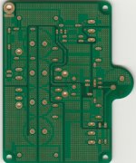
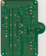
Agreed. I have attached 3 images of the boards I have.
One note before we begin: I read in the ACA thread that the LED was not necessary for a properly functioning amplifier. So, to my untrained eye, can I insert the 499 ohm resistor (call it R16) into the spot for the LED and form the RC filter with C103. Would save a lot of work and worry.
TA, I read your reply to my PM, and the only caveat (I see) to the above is that you quote that a cut needs to be made in a place that leaves C103 connected to the drain of V101. I assume this means directly connected to the drain of the JFET, rather than passing through the resistor first, as you show in your aca16 mod schematic with the 200 ohm resistor.
Regards,

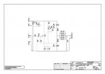
View attachment ACA-AMP_V1_SCH.pdf
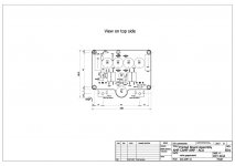
View attachment JPS ACA layout.pdf
One note before we begin: I read in the ACA thread that the LED was not necessary for a properly functioning amplifier. So, to my untrained eye, can I insert the 499 ohm resistor (call it R16) into the spot for the LED and form the RC filter with C103. Would save a lot of work and worry.
TA, I read your reply to my PM, and the only caveat (I see) to the above is that you quote that a cut needs to be made in a place that leaves C103 connected to the drain of V101. I assume this means directly connected to the drain of the JFET, rather than passing through the resistor first, as you show in your aca16 mod schematic with the 200 ohm resistor.
Regards,

View attachment ACA-AMP_V1_SCH.pdf
View attachment JPS ACA layout.pdf
Does the system allow to pdf images to be uploaded, I am sure I have seen them before. Can someone help me post an actual image.
I noticed I could click on the link and then save, and then the pdf would open. Is this the way it works with pdf files compared with jpg or others?
Thanks for the help, hope we can continue with what is posted.
Regards
I noticed I could click on the link and then save, and then the pdf would open. Is this the way it works with pdf files compared with jpg or others?
Thanks for the help, hope we can continue with what is posted.
Regards
I'm sorry to say that this particular board layout does not offer a reasonable way of inserting the dropping resistor, R16, prior to the positive terminal of C103. There is a rather large power plane which would need to be selectively carved up with an Xacto blade or even a Dremel tool. Since we are looking at the bottom layer, I can only assume that the top layer is similarly arranged, due to the pattern of vias. This layout style is, to be quite frank, a bit of an affectation which offers no real benefit to performance.
Sorry, I guess we were posting at same time.
So choices are to just build and enjoy as a regular stock kit ( 20 V or so). Would you still recommend a linear PS, or power with the wall wart or small smps. It is DIY live & learn as you go. Should be a useful building excercise.
Thanks for your help,
MM
So choices are to just build and enjoy as a regular stock kit ( 20 V or so). Would you still recommend a linear PS, or power with the wall wart or small smps. It is DIY live & learn as you go. Should be a useful building excercise.
Thanks for your help,
MM
The ACA can still benefit from a good linear power supply. Since it is a single-rail design, a typical transformer with dual secondary windings may be used to build a quasi dual-mono PSU. You could still safely use 18V secondaries to get around 22V to 23V power on the board.
I can see a way to carve up the power plane and use the LED resistor as a substitute for R16. It's more work than I would care to take on, especially since the cuts need to be duplicated on the top side of the board. There is a chance of making the board unusable in the process. Then you need to repeat the process for the second channel.
I just finished building a stereo ACA with premium parts, I used the schematic and parts list described in this thread. It is in a Hafler DH-200 enclosure with a Meanwell SMPS power supply mounted inside the case.
It is currently playing music, breaking in, about 5 hours old right now.
What do you set bias to for this amp? I set both channels to 12 vdc at pin 2 of Q1. I thought I read you were setting it to 12.4 vdc.
Is this your recommended setting?
It is currently playing music, breaking in, about 5 hours old right now.
What do you set bias to for this amp? I set both channels to 12 vdc at pin 2 of Q1. I thought I read you were setting it to 12.4 vdc.
Is this your recommended setting?
Nice, the DH-200 is a great old amp, and a very suitable chassis.
The bias current of the ACA is set by the resistor values R1 through R4, and also R15. With the values I'm using, I have seen 1.6 Amps quiescent current in all of my boards. The adjustment is for the voltage at the Drain of Q1, which I like to set at 1/2 Vdd, plus 0.4 V.
The bias current of the ACA is set by the resistor values R1 through R4, and also R15. With the values I'm using, I have seen 1.6 Amps quiescent current in all of my boards. The adjustment is for the voltage at the Drain of Q1, which I like to set at 1/2 Vdd, plus 0.4 V.
Why +0.4 V? Won't you have minimal distortion at full power with the bias at 1/2 Vdd?Nice, the DH-200 is a great old amp, and a very suitable chassis.
The bias current of the ACA is set by the resistor values R1 through R4, and also R15. With the values I'm using, I have seen 1.6 Amps quiescent current in all of my boards. The adjustment is for the voltage at the Drain of Q1, which I like to set at 1/2 Vdd, plus 0.4 V.
Why +0.4 V? Won't you have minimal distortion at full power with the bias at 1/2 Vdd?
The ACA clips softly on positive excursions of the output. The 0.4V offset gives slightly more output before you hit the rails (hard clipping).
Howdy to all,
I just remounted the amp camp in a B&K ST-202 case which has larger heat sinks than the ST-140. I never used the case that came with the kit, just the heat sinks. I just bolted the kit heat sinks to the case ones. I am using an Antek AS-3225
transformer with the 25 volt secondaries set up as dual mono. I ran the output of each bridge rectifier through a Hammond 159ZJ choke, which is a 10 mH 5A choke. That goes to 20,400 uf (3X6800 uf caps) of filter caps with .2 uf poly by-passes for each channel. Wanted to add another 6800uf to each side, but just ran out of space. I am only getting about 22.5 volts on the rail under load, but it is nice and quiet. I have run this amp on the 24 volt brick, but I like this linear supply better, sounds more solid. I have a 1000uf Silmic II for C4. For Q1 I have a IRFP 140, and for Q2, a IRFP 044, with 12.7 on the bias. I also ran the grounds to an inch and a quarter square of copper, 1/4 inch thick, which is isolated from the chassis with a nylon bolt. The purple shield from the transformer is bolted to the actual chassis, together with the power ground via a CL-60.
I have found that isolating the ground that way seems to add some clarity and dimension to the sound in my setup. Also have 4700uf 63 volt Nichicon for C1, a bit big, but fits. It has been playing for 45 minutes and the rear sinks are warm, but not hot.
It sounds good enough to put up the solder and iron for a spell, and work on fixing our broke dishwasher :^)!
- Home
- Amplifiers
- Pass Labs
- ACA amp with premium parts


