ACA-220 v2
One of the things I was hoping to achieve with my newer ACA builds was an amplifier in one chassis with just a pair of ACA PCBs that sounded as good or perhaps better than my ACA parallel bridged monoblocks. I took two different approaches toward this goal. The ACA-220 v1 was one approach, and worked quite well. The second approach was to increase both the rail voltage and the transconductance of the power MOSFETs Q1 & Q2.
For v2, the PCB components were updated as follows:
Q1, Q2 - IRFP140
R16 - 499Ω
Deceptively simple, but the remainder of the improvement was to come from the power supply.
The results were worth the effort in the end. V2 has a more lifelike 3-dimensional soundstage, bass that extends deeper yet feels completely integrated with the rest of the music, and an ease of tonal clarity and dynamics that exceed what I have been hearing with the monoblocks. Most importantly, music from this amp is engaging to the point of making me forget whatever else may have been on my mind as I sat down to listen. With this amp I am able to dial up my volume control a little further, and the sound simply extends both forwards and backward in my listening space without the noticeable compression that the original ACAs tended to exhibit when pushed near their power limit.
The journey to achieving the V2 sound proved to be a bit longer than originally anticipated. Sometimes that is part of the fun. I originally wanted to get around 30V power rails for the amplifier circuit, but that goal proved elusive. I started with a pair of 200VA transformers with 25V secondaries, a set of 24000 uF, 63V reservoir caps, and 0.25Ω power resistors after the reservoirs. Didn't work. I barely got 30V at the reservoir caps, sometimes less, and there was a noticeable hum from the power supply. Aside from the faint hum, the imaging didn't seem to lock in place, as it has with V1. The transformers themselves were losing almost 2 Volts in their secondary windings, and the bridge rectifiers were eating another 3+ Volts. Substituting the newer Vishay rectifiers that I listed in my BOM for V1 gave a small but noticeable and repeatable improvement, resulting in 30.2 Volts at the reservoir caps. Increasing the power resistor to 1.0Ω also gave a noticeable and repeatable reduction in hum from the power supply. The 1.0Ω power resistors also provide a convenient way to measure the supply current entering the amp – 1.6V translates to 1.6 Amps. The 1.6A measurement also appears with the appropriate voltage across the 1.5Ω power resistors in the V1 build.
Finally I installed a 300VA transformer (Antek AS-3224) with 24 Volt secondaries and got the same 30.2V at the reservoir caps, but an improvement in sound. Yes! On the right track. Now that I had settled on a lower voltage at the reservoirs, I changed them to the same 36000 uF, 40V caps used in V1. The final piece of the puzzle was to look at the CRCRC configuration as a big C followed by two cascaded RC filters. The V1 build has 1.5Ω / 10000 uF as its first RC. When I changed the V2 build to have 1.0Ω / 16800 uF as its first RC, the sound I had been chasing fell in place. The voltage at the amp power rails is 28.4V, and I have set the Vds of Q1 to 14.4V.
There seems to be a common agreement among folks who have built both the ACA and one or more of the larger FirstWatt clones, that while bridged ACA monoblocks sound greater than the sum of two amps would suggest, the larger FW clones transcend this sound in different ways. I suspect that V2 may bridge some of this gap between the different types of amps. I intend to find out, and have PCBs and parts for both the Aleph J and M2x.
My builds are as close to the 6L6 guides as I can get, but our paths are similar.
I started with 2 ACA's, working on an Aleph J now, and have parts on hand for an M2x. Decided not to mess with my ACA's until I get something else going.
I will be watching for your progress on those builds as well.
BTW, I too noticed compression setting in from my ACA's when the volume knob of my unity gain preamp got a little too close to 11.
Hi James,
thanks for the excellent tuning proposal, it is working great in my two ACA's. I was just surprised, that I have to increase the attenuation of my preamp after the tuning, so my suspect is R12 with 20K is overcompensating the performance increase of the reduced feedback and increased current.
Is there a balance between the feedback loop and the input resistor I need to respect or may I simply choose a lower Value for R12 somewhere between 20K and 10K. (As this are my daily listening devices I am hesitating to disassemble it frequently)
Andreas
The amount of feedback in the ACA is determined by the ratio of R11 and R12. While this ratio is not set in stone, it seems best to keep the input resistor R11 relatively low. The stock values for R11 and R12 were 10k and 68k Ohms until the more recent version that is currently being sold in kit form, where R12 was decreased to 39.2k.
I originally purchased two ACA kits and planned to bridge them to drive my old Vandersteen 2C speakers. Having two amps to experiment with helped me determine a better setup for my speakers and preamps. My Audible Illusions Modulus 3A, which is an all tube preamp, initially had difficulty driving the stock ACA to the same volume as I was able to achieve with my other preamp, a Naim NAC 82. I figured the low input impedance of the ACA was part of the issue. Even though the Audible Illusions uses both triodes of a 6922 in parallel to drive its output, it still has an output impedance of about 600 Ohms. I chose to double R11 to 20k, and picked a value of 90.9k for R12 based on what I had seen in the Zen V4 schematic. The ratio I'm using is very close to that and lowers the feedback compared with ACA v1.6. Comparing one amp in stock form to a second amp with the new values showed a definite improvement in volume and dynamics, especially when the resistance of R3 || R4 was lowered. I eventually added 10 pF in parallel with R12, which helped to smooth out the top end as the amp was being driven hard.
Once I switched both amps to parallel bridged configuration, all the pieces finally came together. In this setting I think it's definitely better to have a larger value for R11.
I have seen others try different values, including eliminating R12 altogether. You may certainly feel free to try your own tuning and see how it affects the sound in your system.
Gentlemen: is anybody of you interested to have these PCBs?
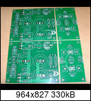
https://abload.de/img/aca_10vkss.jpg
3 sets of them (so: 6 ACA PCBs and 6 rectifier-PCBs).
The price is: 25€ (worldwide, unregistered shipping is included).
The PCBs are tested (refer to this post: https://www.diyaudio.com/forums/pass-labs/328357-aca-amp-premium-11.html#post5723327) and reflect TungstenAudios "changes / improvements".
If you like to have the PCBs: give me a PM. "First come - first serve".
Best regards - Rudi_Ratlos
Attachments
For those experiencing hum with a linear power supply, try a decoupling network between the incoming Voltage rail and the Drain of Q4, the 2SK170. Try 1K Ohm and 220uF or 470uF, but it all depends on how much hum you have. If using a higher rail Voltage, it's also good to limit the Voltage to Q4.
The ACA definitely runs well with higher voltages and linear power supplies. Higher supply voltages may be challenging with the standard PCBs available from the diyAudio store. The main issue is the lack of a dropping resistor between the supply rail and the drain of Q4 (input JFET). I was fortunate to have a few custom boards that had this resistor included as R16, which is referred to in post #121. The resulting decoupling network was 499 Ohms into 100 uF. In that same build I also substituted IRFP140s for the customary IRFP240s. I was very pleased with the results. When I get around to building a higher voltage ACA, I will probably increase R16 to 1.0k or 2.2k.
My most recent efforts have been with a M2x clone of the FirstWatt M2. The replaceable input stage modules offer a number of opportunities to experiment with different input devices, as well as local power supply bypassing. Two of the boards I have tried so far have local power bypass caps (Mtn View and Tuscon), and exhibit improved imaging and low level detail compared with the simpler JFET front end (Ishikawa). I have a prototype of an enhanced JFET front with added power bypass in the works, and it will be interesting to compare this with the original.
As with my ACA builds, I spent extra care and some experimentation to get a low noise power supply. My efforts were rewarded with an exceptionally quiet amplifier.
Last edited:
Hmm I built the Diy Shoppe PS supply for my F6 build.
Both 100% stock as per 6l6's excellent guides.
There are ZERO noises.
Ears as close to the dustcaps as I can possibly get them on my tannoys.
Power on / Power off .. Volume pot to max or to minimum ...No audible difference
Astounding to me.... sometimes the wheel simply doesn't need reinventing ?
Both 100% stock as per 6l6's excellent guides.
There are ZERO noises.
Ears as close to the dustcaps as I can possibly get them on my tannoys.
Power on / Power off .. Volume pot to max or to minimum ...No audible difference
Astounding to me.... sometimes the wheel simply doesn't need reinventing ?
Hmm I built the Diy Shoppe PS supply for my F6 build.
Both 100% stock as per 6l6's excellent guides.
There are ZERO noises.
Astounding to me.... sometimes the wheel simply doesn't need reinventing ?
What he said"
")
My F6 is silent into Fostex back loaded horns.
What he said"
My F6 is silent into Fostex back loaded horns.
Mine as well,F6,M2,AlephJ,F7ish.All with the same diy store supply,all dead silent.
Sometimes it really is best to go back and re-read some of the source material. In this case:
My quest for a better sounding ACA seemed to follow an inevitable trajectory of more iron and more power supply capacitance.
Followed by:As a consumer, you want the best sound you can get. You can accomplish that through critical listening. As a secondary goal, we all like to get what seems to be good hardware value, and we want to know that that the manufacturer has actually put some real money into the product which costs a small fortune. If you can read the specs or look under the hood, the power supply, being one of the most expensive parts of the amp, usually is a good indicator. It should be the biggest and heaviest part of the amplifier.
And finally...Mono operation is very desirable in high end systems, but of course it is expensive. A modest compromise is offered by "dual-mono" operation, in which two channels share the same chassis and power cord, but have separate transformers and supply capacitors. This achieves much of the isolation desired at lesser cost.
...
Most of the time, you want to see a total of at least 100,000 microfarads, which for our example gives a ripple of about .6 volts. This is pretty good, representing about 1% of the total supply voltage. Smaller amplifiers can get by with less, big amps require more.
Big electrolytic capacitors have a small amount of inductance, or "coilness", in their makeup, a result of the spiral winding of the capacitive film. To reduce the effect of this inductance, film capacitors which have low inductance are often placed in parallel, so that at high frequencies the current flows a little more easily.
The above were all excerpted from Nelson Pass' article "Power Supplies," which is available on his website PassDiy.com.Active linear regulation is a great way to make the supply voltage constant. Unfortunately it is not usually done properly. In the past, some amplifiers using active regulation have been criticized for a lack of apparent dynamics, and this has given the technique a lesser reputation than it deserves.
Properly done, linear regulation has to go beyond the cursory requirements of the amplifier ratings. The regulator should be capable of ten times the current of the continuous output of the amplifier channel. The regulator should be preceded and followed by large capacitances with values comparable to those needed for unregulated circuits. The transformer size still needs to be as big as that used in an unregulated circuit.
Approached in this manner, linear active regulation delivers the goods.
My quest for a better sounding ACA seemed to follow an inevitable trajectory of more iron and more power supply capacitance.
Last edited:
My quest for a better sounding ACA ....
what "better sounding" means for you .
.
Other points
Just going to jump in here for a moment. I have stayed with a single chassis ACA, and a separate linear 22v supply, dual mono sans transformer. I also have a very similar path of mods, also a AI pre initially. This required the same R11/R12 ratio, in my case 28k/100k foil resistors. My 91db speakers(VR-5) are a relatively easy load for the ACA. Since my disk player(Meridian) and phono amp(VPI/McCormick) are free of caps in the signal path, and coupled with the efficient speakers, I was willing to try a passive preamp. This was suggested by Zenmod, one of the greedy/big boys. I must admit, this was an advance in sound improvement/purity exceeding most of the improvement/mods done to the ACA. Those mods include 100k uf CRCRC PS, 10uf MKC input cap, 3300uf silmic output cap/auricap bypass, foil feedback, tantalum stoppers, etc. etc. Tried a lot of items.
It pays to heed what and how you feed your ACA also. Sorry, a little off the subject.
The quality of the source and all intervening stages definitely matter. As I was in the process of evaluating a pair of the original ACAs that I built as monoblocks, I also built a new power supply for my preamp an NAC 82. The result was astonishing. The soundstage grew deeper front to back, taller and wider. Instruments were better defined.
Later, as I was working on my first Hafler chassis ACA, I built a similar power supply for my Naim XCD2 CD player. Though not as dramatic as with the preamp, the improvement was still noticeable.
I've always enjoyed spinning vinyl from time to time as well. I have an older VPI HW19 mkII with a Linn Itok LV II tonearm and a Rega Exact cartridge. It has that old school sprung suspension sound that I like. I have a second turntable dedicated to playing 45 rpm LPs, a Rega P3-24 with the Rega RB301 arm and Exact cartridge. Given that both turntables use the same cartridge, it's interesting to hear the subtle differences with the same recording pressed for 33 1/3 vs 45 rpm. Source definitely matters.
Attachments
Last edited:
I could suggest an Active supply Regulation.
Have done it in my ACA build. Idea was taken from the ZEN Article Ver3.
Had nothing to complain. Amp sounded to like a little Aleph J. No hum.
At 5W outputpower Regulation will not be such a big Problem.
Made the Regulation with IRFP Mosfets bolted to the groundplate, so it was really reliable. And one Regulator for one channel so i have what i call pseudo dualmono
Sold the ACA later, Aleph J had more drive into my Speaker.
I have been considering some form of active supply regulation for the ACA, but I wanted to try a straight CRCRC method first. While the basic implementation of an IC based regulator left a little to be desired, there are certainly improvements that might make that more viable. I think it would also be possible to build a higher performance discrete regulator that would be very satisfying. Judging by some of the most successful implementations, when done properly it would be about the same size as the main ACA board. As such, a full discrete regulator implementation for the ACA is out of my wheelhouse for the time being.
I am more interested in the various forms of capacitance multipliers, mainly because they are simple and compact, and perhaps somewhat more in line with the original tenants of the ACA. An IRFP Mosfet based C-multiplier such as the one used in Zen Variations 3 would be an example. From there it would be a short step to go to a modulated C-multiplier such as the one in Zen V4. I have my own version of a Complementary Feedback Pair which I have used to modify two of my original Hafler amplifiers (still available for use). I also used a CFP to implement a tracking regulator that is still in use in the front end of several models of medical Ultrasound machines that I worked on back in the day.
Lots of things to work on. Much of my energy is currently being channeled toward IPS designs for the M2x clone. ACA variations are still on the table, though.
Forgive my shaky theory (I mostly just follow the instructions) but I assume we are talking about substituting linear supplies for the bricks provided. Given the amount of space available in the ACA chassis, would there be any mileage in building a little super-regulator for each channel and retaining the original bricks, or are the latter a lost cause? TIA.
I am interested in the regulation issue. While it has some attractive possible benefits, I have gone back to crc as I found I liked the sound better. This may be due to the added final c capacity, being I just removed the last R, leaving 60k uf in the final bank.
Last edited:
Most of my work on the ACA recently has been with linear supplies, but per channel filtering and active regulation may still be applied to an SMPS such as the original bricks that are sold with the ACA kits. My first mods included a modest addition of local power supply bypass capacitance by substituting the 100 uF Aluminum polymer cap for the original 10 uF Elna Silmic. That little tweak is part of what improved the sound. As has been mentioned before, the really big upgrade one can make with the original ACA (premium components or not) is to build a second one and bridge it in one of the two ways mentioned.
The issue with adding some form of active regulation to a SMPS is the voltage that is 'eaten' by the regulator. A Mosfet based C-multiplier will drop about 4 Volts, and a bipolar CFP (or Sziklai pair) will drop about 2 Volts depending on how it is set up. If you have a 27V or 36V SMPS, then no problem, as long as you don't put too much capacitance directly on the PSU output. I now prefer running my ACAs at higher voltage and eventually plan to try some different options with 150 or 200 Watt units inside the Modushop Mini Dissipante 3U case. The thick front panel will make a nice heat sink for the pass transistors.
The issue with adding some form of active regulation to a SMPS is the voltage that is 'eaten' by the regulator. A Mosfet based C-multiplier will drop about 4 Volts, and a bipolar CFP (or Sziklai pair) will drop about 2 Volts depending on how it is set up. If you have a 27V or 36V SMPS, then no problem, as long as you don't put too much capacitance directly on the PSU output. I now prefer running my ACAs at higher voltage and eventually plan to try some different options with 150 or 200 Watt units inside the Modushop Mini Dissipante 3U case. The thick front panel will make a nice heat sink for the pass transistors.
- Home
- Amplifiers
- Pass Labs
- ACA amp with premium parts