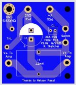
I'm thinking to fab some PSU Filter boards inspired by the newest VFET design for a pair of ACA monos I'm building soon.
This is a 45x40mm PCB. It will require drilling the bottom of the ACA chassis.
Idea is to run PSU+ and GND to the board. Then a pair of wires to the switch. Then one wire with V+ to each amp PCB (one per side of this PCB).
Comments?
This is a 45x40mm PCB. It will require drilling the bottom of the ACA chassis.
Idea is to run PSU+ and GND to the board. Then a pair of wires to the switch. Then one wire with V+ to each amp PCB (one per side of this PCB).
Comments?
Attachments
I suggest you wait until the other half of the VFET lottery has completed, just to see whether the N-VFET amp uses a different PSU filter than the first-to-be-released P-VFET amp. If it is different then you'll have to decide whether you want to copy the P-VFET-PSU-filter, or copy the N-VFET-PSU-filter.
And perhaps it might be possible for you to lay out a super-duper-universal-VFET-filter PCB, which includes both designs. Perhaps as PCB options with wire jumpers or something.
And perhaps it might be possible for you to lay out a super-duper-universal-VFET-filter PCB, which includes both designs. Perhaps as PCB options with wire jumpers or something.
The big improvement is going to come from building monoblocks. That way you get a separate power supply for each channel, and get to choose how to bridge the two boards in each amp to best suit your speakers.
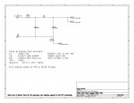
The filter boards are a nice extra. A simple CLC, so no need to over-think the issue. The basic design as used by the VFET lottery amp will be fine. If you choose to increase the second C , that can make sense as well. The inductor will reduce the startup current into any bulk capacitance you may add.
The filter boards are a nice extra. A simple CLC, so no need to over-think the issue. The basic design as used by the VFET lottery amp will be fine. If you choose to increase the second C , that can make sense as well. The inductor will reduce the startup current into any bulk capacitance you may add.
sorry for that stupid question...but i not clear today...i do not want to change the gain setting.
i plan to build an integrated ACA. how to implement the alps 10k pot?
just at the start of the amp and connect the "slider" to the R11 10k?
chris
Hi Chris,
I didn't mean to suggest for you to change the gain of your ACA, I had just mentioned that I had done so to accommodate the higher gain of my tube preamp. You might find that a buffer like the Pass B1 buffer will give you better sound than just a 10K pot as input to your amp. Many people have had satisfaction using the B1. You could also add a selector to open the flexibility of having more than 1 input into your amp. I always preferred the sound using a buffer or preamp as my input, but you could hook up the pot and see if you like the sound. That is the adventure of DIY. A lot will depend on your source.
Den
I'm thinking to fab some PSU Filter boards inspired by the newest VFET design for a pair of ACA monos I'm building soon.
This is a 45x40mm PCB. It will require drilling the bottom of the ACA chassis.
Idea is to run PSU+ and GND to the board. Then a pair of wires to the switch. Then one wire with V+ to each amp PCB (one per side of this PCB).
Nelson Pass just revealed that he has revised the SMPS filter for his Sony VFET DIY amplifier kit. This apparently was necessary to accommodate the N-channel VFET boards, coming soon. See post #1538 in the Sony VFET Builders Thread (here)
You may want to include the same modifications in your PCB, that he has included in his.
I don't think he has posted a schematic or a photo of the board yet.
Maybe a parts list update ?
Why so powerful transformer(s) ?
It is just a 5W (class A) amplifier. QC is (if I remember correctly) about 1.8A so for 24V we have ~50VA. I propose halogen lamp transformer (24VAC 50VA). They are toroidal, cheap and very common (at least here in Athens Greece) for powering 24V halogen spot lamps. Of course a capacitors bank is necessary.
In YouTube I found a nice video for this amplifier from *audiophile DIYer". I like very much the idea of incorporating PSU+ACA in one pcb.
Elias
Last edited:
28 VDC linear power supply (rated at 7 amps). I will be running two ACA's in balanced mode. Each amp will have its own separate power supply. Before I solder these MOSFETs in place, I want to make sure I am not making a mistake. I have other MOSFETS available, even IRFP040s if need be. I want to make the best "Premium ACA" I can with the parts I have. I could build other power supplies if needed.
Well, I can not explain clearly the operation of SRPP stage (and ACA is a SRPP amp after all), but Q1 is the main amplifying device and Q2 is like a current source.
To simplify things imagine if we replace Q2 and its surrounding circuitry with a big resistor (lamp) like in "ZEN lite". Then Q1 is the only active device that affects the sound and its Gfs and Ciss determines how the amp sounds, its damping factor, its freq. range and so on.
Higher Gfs - lower Rout
Lower Ciss - extended freq. range (of course it's not that simple, Iout will also play a role here, as it works together with Qg, the total gate charge).
So, in general, the higher the current and Gfs, the lower the Ciss, the better the sound, especially for SE Class A.
I'm sure someone more knowledgeable will explain it better and correct me if I'm wrong.
^ Yes, this is my understanding as well. The "current source" portion of the ACA is more dynamic, but not quite the full Aleph implementation. I think the IRFP140 is a good application for Q2 in the ACA.
I have used the FQH44N10 in my F6, also running at a higher than normal voltage to bring out the higher Gfs of the part. It worked very well. Plenty of grunt to power my Vandersteens. In the ACA, I expect it to contribute to better dynamics and clarity. The higher voltage (28V) linear supply and the reworked R1 through R4 values improve the quiescent current and power delivery.
I have used the FQH44N10 in my F6, also running at a higher than normal voltage to bring out the higher Gfs of the part. It worked very well. Plenty of grunt to power my Vandersteens. In the ACA, I expect it to contribute to better dynamics and clarity. The higher voltage (28V) linear supply and the reworked R1 through R4 values improve the quiescent current and power delivery.
Thank you to both experts.
so for the CCS its better to use the best PowerFET with high gfs and less RDSon to deliver the best possible "current" --> FQH44N10
Q2 is the "sound machine"...actually i have the IRFP140 and i like it.
the other ACAp is with Q1+Q2 IRFP040 and its a bit different...but i will report my changes.
thx chris
- Home
- Amplifiers
- Pass Labs
- ACA amp with premium parts