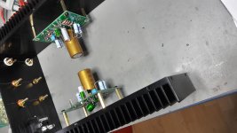
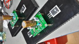
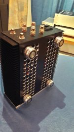
It is really important not to short that steel transformer mounting bolt between the top and bottom plates. That forms a shorted turn around the outside of the toroid. I mount my toroidal transformers with nylon bolts to make sure this never happens.
You can happily keep the 300VA transformer by lifting the top plate of the chassis above the heatsinks with some spacers and longer screws. That will also allow more airflow.
You can happily keep the 300VA transformer by lifting the top plate of the chassis above the heatsinks with some spacers and longer screws. That will also allow more airflow.
I was attempting to do the small signal analysis in CircuitLab today for my new build. I recreated the schematic with TungstenAudio's values and ran the DC analysis. I got some really strange DC voltages. I have checked all I know to check. I am not seeing anywhere near 12V Vds on Q1. Anyone know what am I doing wrong?
Attachments
In real life, the builder twirls the shaft of P1 left and right, hoping to find a setting with acceptable DC balance. See steps 51 and 52 of the Build Guide. How are you duplicating that procedure in the circuit simulator?
The model of P1 in the circuit is set at the midpoint 2500/2500Ω. This is the first time I have used CircuitLab software. Either I have something modeled incorrectly in the schematic, or the DC modeling capability within CircuitLab is just not very good. I was hoping to get this circuit modeled so that I could see what the effects of changing components/values will have.
Then you will have to figure out how to tell Circuit Lab: "Set the potentiometer rotation to 10%"
Then you will have to run Circuit Lab fifteen or twenty times, with different settings of potentiometer rotation, until you get the same result in simulation, as the Build Guide recommends in steps 51 and 52 for real life.
edit- it might speed things up and require fewer simulation runs, if you made a little plot of potentiometer rotation vs voltage, adding a new dot on the plot every time you run a new simulation. Then you could interpolate and extrapolate the plot to get a very good estimate, simulate there, plot, and get an even better estimate, etc.
_
Last edited:
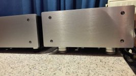
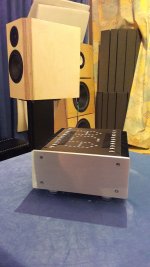
Very nice looking build.
Thank you!
In any case watch out NOT to short the transformer through the bolt against the top lid...
It is really important not to short that steel transformer mounting bolt between the top and bottom plates. That forms a shorted turn around the outside of the toroid.
Thank you both for pointing that out. It makes sense, but never would have crossed my mind. If anything else sticks out in the build, please let me know!
You can happily keep the 300VA transformer by lifting the top plate of the chassis above the heatsinks with some spacers and longer screws.
I considered using some standoffs to raise the top plate, but in the end decided I would rather keep the chassis tightly enclosed like it's supposed to be and ordered a 200VA model.
The model of P1 in the circuit is set at the midpoint 2500/2500Ω.
If it's helpful, in my build the pot ended up turned 30* right of center (14V at pin 2 of Q1, 28V power supply). Small movements caused a pretty big swing in voltage, but it is a single-turn pot so that might have something to do with it. Good luck with the model!
Then you will have to figure out how to tell Circuit Lab: "Set the potentiometer rotation to 10%"
Then you will have to run Circuit Lab fifteen or twenty times, with different settings of potentiometer rotation, until you get the same result in simulation, as the Build Guide recommends in steps 51 and 52 for real life.
edit- it might speed things up and require fewer simulation runs, if you made a little plot of potentiometer rotation vs voltage, adding a new dot on the plot every time you run a new simulation. Then you could interpolate and extrapolate the plot to get a very good estimate, simulate there, plot, and get an even better estimate, etc.
_
I have done what you recommended by replacing P1 with two resistors and then varying the values and running the DC solver. The changes in voltage are not in the range that change the bias voltage enough. I must be missing something, but I have not found it yet. Thanks for the reply.
Hi Rocket,
On your posted simulation schematic, check the values you have for R1,2,3,4.
It looks like you have for instance, R1 as 470m ohm, and it should be .47 ohm.
Likewise, the other resistors 2,3,4, are not mega ohm as they are in your pdf.
R2 should be .47 ohm, R3, .68 ohm, and R4, .50 ohm.
Try those values in the sim and see how it reacts")
On your posted simulation schematic, check the values you have for R1,2,3,4.
It looks like you have for instance, R1 as 470m ohm, and it should be .47 ohm.
Likewise, the other resistors 2,3,4, are not mega ohm as they are in your pdf.
R2 should be .47 ohm, R3, .68 ohm, and R4, .50 ohm.
Try those values in the sim and see how it reacts
To all who have been following this thread, know that I'm grateful to be part of this community. I am especially humbled by the praise of the one and only N. Pass who has so generously given of his designs and his experience.
On board, drop-in replacements
C1: 4700 uF, 35V; Nichicon KG series "Gold Tune"
C2: 1000 uF, 16V; Nichicon RNL series Aluminum Organic Polymer
C4: 100 uF, 35V; Nichicon RL8 series Aluminum Organic Polymer
R11: 20 kOhm, 1/4W, 1% metal film
R12: 90.9 kOhm, 1/4W, 1% metal film
On board add-on components
R4b: 2.0 Ohm, 2W, 2% metal oxide; added in parallel w/ R4
C101: 10 pF, 500V, 5% Silver Mica; added in parallel w/ R12
Off board substitution
Bridging Resistor: 68.1 kOhm, 1/4W, 1% metal film
Note that I left C2 as the 10 uF, 25V Elna Silmic II, and have been quite pleased with the overall results. Recently I happened to acquire a Naim NAP 150, and discovered that it also uses the exact same component for its input coupling capacitors. Given Naim's extremely selective practice for their components, it seems that we are all in good company.
I'm getting things together to build two ACA's with premium parts. I plan to use them in bridged mono mode with some KEF LS50 speakers. They are medium sensitivity and, with digital audio sources, a little bright. Is the following list still a good recommendation?
C1: 4700 uF, 35V; Nichicon KG series "Gold Tune"
C4: 100 uF, 35V; Nichicon RL8 series Aluminum Organic Polymer
R3: 0.68 Ohm, 3W, 2% metal oxide or film
R4: 0.50 Ohms, 3W 2% metal oxide or film
R11: 20 kOhm, 1/4W, 1% metal film
R12: 90.9 kOhm, 1/4W, 1% metal film
On board add-on components
C101: 10 pF, 500V, 5% Silver Mica; added in parallel w/ R12
Off board substitution
Bridging Resistor: 68.1 kOhm, 1/4W, 1% metal film
Most capacitors are posted with brand and models but the resistors are not. What brands and models do you think I should acquire for the following?
R3: 0.68 Ohm, 3W, 2% metal oxide or film
R4: 0.50 Ohms, 3W 2% metal oxide or film
R11: 20 kOhm, 1/4W, 1% metal film
R12: 90.9 kOhm, 1/4W, 1% metal film
Bridging Resistor: 68.1 kOhm, 1/4W, 1% metal film
C101: 10 pF, 500V, 5% Silver Mica; added in parallel w/ R12
Also, is 12.4V still a good bias voltage? This is my first, and largest, electronics build in many years and I want to get it good the first time around. If all goes well, I plan on building a preamp next, maybe a Korg NuTube.
Thank you for all the help and knowledge.
..ACA premium..gain to low
Hi
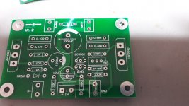
i build my ACA p with nearly all components what TungstenAudio did. i use this zereozone board and the space for some parts is smaller. at this board a diode is implemented and i wrote in the ACA thread that this is useless for me and the sound is not really nice with the diode. the idea to use this place for a resistor to build the hp filter in the drain of the N JFET is not possible because the layout show me that this is before R7 10k (collector of ZTX450). so this update is not done.in pic 1 you see this small pcb.
psu 24V- SMPS meanwell 150W for both channels
DC bias is 12,34V
all resistors are vishay dale 0,5W 1%
NJFET is BF245B
ZTX450 as CCS
C3 is 10µF nichicon muse
C2 is RLN nichicon polymer
C4 is the same i use in the normal ACA = Rubycon ZL 820µF/50V // foil 100nF
C1 is a Nichicon FW 6800µF/35V this give me 4,5A ripple c. @ 10khz instead of 2,9A from the gold tune LKG
parallel to C1 is use 10µF muse bipolar (green) and a 100µ nichicon muse green
C5 is parallel to R12 = Rf and a 10pf silver mica
all gate stopper are 120R instead of 100R
first step i get to low bias current 1,43A and a gain of 8,1dB.
i use 10k R11 and Rf 37,4k ?
i solved the bias current as Tungsten wrote with a 2R resistor in parallel to 2x.068R and it works great. thanks for that !!
i re think my feedback setup and realized that it s for mono block use (thats my target) wrong because it must be R11 20k and Rf 90k. so i add a second 10k at R11 and get 20k and i add a 47k to the 37k4 to Rf to get about 84k .
now i got just 9dB gain. why?
is the C5 10pF (// to Rf) so hard influence the ratio of the amp? 20k - 90k = 4,5 --> is about 13db....real 11,5db what i read?
the amp is running since 3 weeks and still with lower gain as the other ACA (11,5dB) but the improvements are nice. more texture, more focus and a step smarter to delivery live moments.
thanks for your time
chris
Hi
i build my ACA p with nearly all components what TungstenAudio did. i use this zereozone board and the space for some parts is smaller. at this board a diode is implemented and i wrote in the ACA thread that this is useless for me and the sound is not really nice with the diode. the idea to use this place for a resistor to build the hp filter in the drain of the N JFET is not possible because the layout show me that this is before R7 10k (collector of ZTX450). so this update is not done.in pic 1 you see this small pcb.
psu 24V- SMPS meanwell 150W for both channels
DC bias is 12,34V
all resistors are vishay dale 0,5W 1%
NJFET is BF245B
ZTX450 as CCS
C3 is 10µF nichicon muse
C2 is RLN nichicon polymer
C4 is the same i use in the normal ACA = Rubycon ZL 820µF/50V // foil 100nF
C1 is a Nichicon FW 6800µF/35V this give me 4,5A ripple c. @ 10khz instead of 2,9A from the gold tune LKG
parallel to C1 is use 10µF muse bipolar (green) and a 100µ nichicon muse green
C5 is parallel to R12 = Rf and a 10pf silver mica
all gate stopper are 120R instead of 100R
first step i get to low bias current 1,43A and a gain of 8,1dB.
i use 10k R11 and Rf 37,4k ?
i solved the bias current as Tungsten wrote with a 2R resistor in parallel to 2x.068R and it works great. thanks for that !!
i re think my feedback setup and realized that it s for mono block use (thats my target) wrong because it must be R11 20k and Rf 90k. so i add a second 10k at R11 and get 20k and i add a 47k to the 37k4 to Rf to get about 84k .
now i got just 9dB gain. why?
is the C5 10pF (// to Rf) so hard influence the ratio of the amp? 20k - 90k = 4,5 --> is about 13db....real 11,5db what i read?
the amp is running since 3 weeks and still with lower gain as the other ACA (11,5dB) but the improvements are nice
. more texture, more focus and a step smarter to delivery live moments.thanks for your time
chris
Attachments
Last edited:
- Home
- Amplifiers
- Pass Labs
- ACA amp with premium parts