Variac said:As far as I can see it needs to be done as shown in the 1.8 wiring diagram.
Well, my suggestion would be that you and Jim should get together, and discuss it, and decide which way it should be, because he just said this with respect to my question today:
The actual location of the resistor is immaterial, you could absolutely put it between the RCA and the switch. Make sure you connect the 39K resistor to terminal 4 and the speaker post to terminal 6.
Which is what I've done, except I've used the 68.1K ohm resistor that TungstenAudio specified.
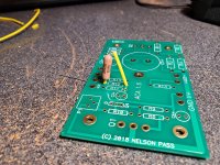
Hi, I finally have all the performance parts for my two Amps. While test fitting I ran into this issue the upgrade for R12 is a Vishay 1/2 watt 90.9k ohms and is a little larger than the pads. I came up with this idea that I have see on older equipment. I figure I will tack on the Mica to the bottom of the board or in between the arch of the Vishay on top. Any thoughts. See Pic.
Mark
Mark
Attachments
Last edited:
If there's something "clever" about the wiring of V1.8, it's that the L&R center pins of the switch are each connected to an input directly so that when that little shunt connecting the top 2 pins is activated by pushing the switch handle down, the 2 channels are shorted together in parallel. Thus we can't have the resistor going from the center pin to the input as in the 1.6, as this would keep the "clever" part from working. Then if you push the handle up, it "cleverly" connects the resistor, and disconnects the shunt.
This is correct. Ignore what I’ve been saying. Wire it as on the 1.8 diagram.
I totally forgot about the parallel connection.
1) Down switch position Parallel Connection (shunted top pins) conecting left and right inputs together. (Parallel mono)
2) Middle switch position - Switch open/off (stereo mode)
3) Top switch position - Amp circuits connected in balanced mode (Balanced mono)
In ACA 16 - Resistor can be on either side of the switch
In ACA 18 - Resistor has to be where it is, because when amps run parallel mode, the left and right rca inputs would be joined together via that resistor if it were in the same position as ACA 16. We don't want this.
If you only ever used Balanced or Stereo it wouldn't matter, it just matters for parallel mode.
I hope all this makes sense and we are on the same page.
Last edited:
This is correct. Ignore what I’ve been saying. Wire it as on the 1.8 diagram.
I totally forgot about the parallel connection.
I wish I knew that before i wired it up the way you said to earlier today...

One problem is that Puma kinda had 2 questions
1. "....Especially as this resistor was originally connected from the switch to a INPUT, and and now it is connected to an OUTPUT."
IMHO this is not a correct analysis, in both 1.6 and 1.8 the resistor is connected between between an output and an input and switched in and out. In the 1.6 we were using just 2 terminals of the switch to connect the resistor into the circuit. The resistor can be on either side of the switch.
The different ways of using the 1.6 as a mono amp required lots of external cable switching.
2. Why can't we hook up the resistor in the 1.8 in either of 2 ways as in the 1.6? Or at least more like the 1.6?
The 1.8 uses 5 terminals of an on-off-on switch to eliminate the need for a lot of the external cables, thus is more complicated. In order to get all the cool hook up options without tons of external cables, the switch has to be used as shown because if it isn't the resistor which is used in the "bridged" function messes up the balanced function as has been mentioned.
Jim was answering question 1 correctly without realizing that the more complicated circuit only works one way as in question 2
Jim 6L6, Pico and I, after tearing our hair as to why, because it is tricky, at least for me, have in the end all explained why the resistor has to be where it is. If you want to have other theories as to how it can be done and still work as it is described on the chassis back panel, this is DIY, you can try them out, but it isn't our job to to evaluate them all. We try to help here in the threads, and maybe there is another way, but what is in the official wiring diagram is the official way that we know works.
Last edited:
Also for using the XLR for balanced input to the amp2) Middle switch position - Switch open/off (stereo mode).
But then the labeling on the back panel would be lying!If you only ever used Balanced or Stereo it wouldn't matter, it just matters for parallel mode.
Last edited:
One problem is that Puma kinda had 2 questions
1. "....Especially as this resistor was originally connected from the switch to a INPUT, and and now it is connected to an OUTPUT."
IMHO this is not a correct analysis, in both 1.6 and 1.8 the resistor is connected between between an output and an input and switched in and out. In the 1.6 we were using just 2 terminals of the switch to connect the resistor into the circuit. The resistor can be on either side of the switch.
The different ways of using the 1.6 as a mono amp required lots of external cable switching.
2. Why can't we hook up the resistor in the 1.8 in either of 2 ways as in the 1.6? Or at least more like the 1.6?
The 1.8 uses 5 terminals of an on-off-on switch to eliminate the need for a lot of the external cables, thus is more complicated. In order to get all the cool hook up options without tons of external cables, the switch has to be used as shown because if it isn't the resistor which is used in the "bridged" function messes up the balanced function as has been mentioned.
Jim was answering question 1 correctly without realizing that the more complicated circuit only works one way as in question 2
Jim 6L6, Pico and I, after tearing our hair as to why, because it is tricky, at least for me, have in the end all explained why the resistor has to be where it is. If you want to have other theories as to how it can be done and still work as it is described on the chassis back panel, this is DIY, you can try them out, but it isn't our job to to evaluate them all. We try to help here in the threads, and Maybe there is another way, but what is in the official wiring diagram is the official way that we know works.
Thank you, Variac, for this detailed explanation AND your "very clever" explanation a few posts back explaining why the wiring for V1.8 must be the way it is for all the possible operational configurations (stereo, parallel mono and bridged mono) to work correctly. Your "very clever" explanation was (finally) the explanation that allowed me to figure out and most importantly, understand why the wiring for V1.8 must be made the way it is shown in the diagram.
I'm sorry for all the "confusion" created by my question(s). I really appreciate everyone being so patient with me and helping out by providing all the explanations. Per my original comment 1 you've referenced above: "....Especially as this resistor was originally connected from the switch to a INPUT, and and now it is connected to an OUTPUT.", yes, this is part of the source of the "confusion" about my question but keep in mind....I didn't understand what I was supposed to be doing with respect to WHY the connections are what they are. I was only following the instructions on the wiring diagram, and when looking at the diagram, it appeared to me I was connecting the output one of channel to the input of another, and that was a concern for me. I didn't understand (again, because I have viritually no domain expertise in electronics engineering) that this how the two channels are, in fact, "bridged" together.
This is why I made the comments a few posts back that when changes are made to the circuit topologies as the design evolves over time, it is really helpful to provide an explanation of WHY the changes are made as well as WHAT the changes are.
But I get it now.
Many thanks to Jim, Tungsten, Variac, and Pico for being so patient and helpful. You guys are great.
Cheers,
Stephen aka PC
Last edited:
Puma Cat
Hope it is clear now.
We all agree now.
It was very confusing at first trying to understand what exactly you needed help understanding.
Hi Pico!
Ha!
Yes. If it was confusing for you guys to understand what I needed help with, you can imagine how confusing it was for me with 3 different people were telling me 2 different things! LOL. It's all good, now. I understand the rationale behind the V1.8 wiring diagram.
Thanks again to the guys here for helping a newbie out. Cheers.
Last edited:
Hi Pico!
Ha!
It's all good, now. I understand the rationale behind the V1.8 wiring diagram.
Thanks again to the guys here for helping a newbie out. Cheers.
Yeah. Don't worry.
Interpreting someone elses circuit design can strain the brain.
I haven't read any of the documentation, I was relying 100% on the information you were giving me.
This hobby challenges the mind.
It's normal to feel confused.
2 picoDumbs said:What an awesome amp design.
I have the original, now I want this one too.
I'm coming into this whole thing late with just the parts and wiring diagrams for version 1.8. I only found out about the ACA when Papa was on as a guest a few weeks back for the SF Audiophile Society Zoom get-together. Given all the various iterations, especially for V1.6 and V1.8 and now this Premium Parts thread, trying to get caught up and have some foundational understanding for this amp has been a lot of work and lot of reading as all the information is scattered among a number of different threads. I've had to kind of make a map of where all the various info is located to be able to find it when needed for reference.
But, as I said before..it's all good, this community is great and I'm having a lot of fun.
Cheers, guys.
- Home
- Amplifiers
- Pass Labs
- ACA amp with premium parts